
Specifications
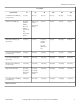


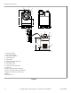


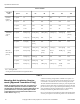

Machine Dimensions [Refer Figure 2 and Figure 3 ]
35 60 80 100 125 150
P 2.9 in. [72
mm]
2.9 in. [72
mm]
2.9 in. [72
mm]
2.9 in. [72
mm]
2.9 in. [72
mm]
2.9 in. [72
mm]
Table 2
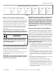
Machine Foundation Requirements
A 6 inch [153 mm] [for 35 and 60 2-speed, L-speed and M-speed
models] or a 12 inch [305 mm] [for all other models] thickness of
4,000 psi reinforced concrete foundation is absolutely necessary
because of the high extract speed and the G-forces exerted.
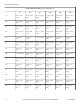
When designing floors or foundations, refer to Table 4 for Floor
Load Data for all model sizes. If the foundation requirements
have been met, proceed to Mounting Bolt Installation Require-
ments section.
NOTE: Do not mount on wooden floors, tile floors,
above ground level, or over basements or crawl spaces
because of the high extract speed and the G-forces ex-
erted.
WARNING
To reduce the risk of fire, serious injury, property
damage and/or death, install the machine on a level
(within 3/8 inch), uncovered concrete floor of suffi-
cient strength at grade.
W787
For new foundations a mounting bolt template is available at ex-
tra cost. For new foundations a bolt-locator fixture or rebar frame
is also available and a preferred option. This rigid welded assem-
bly made of reinforcing rod and mounting bolts is designed to be
embedded in concrete. Refer to Figure 5 .
The machine must be anchored to a smooth level surface so that
the entire base of the machine is supported and rests on the
mounting surface.
IMPORTANT: Do not permanently support the machine
on only four points with spacers. Grouting is required
and spacers must be removed.
IMPORTANT: The above instructions and recommenda-
tions are conservative specifications for a typical in-
stallation based on consultations with a structural en-
gineer. Alliance Laundry Systems stands behind all in-
stallations meeting these specifications. For alternate
installation specifications based on your soil type, lo-
cation, building structure, unique floor geometry, ma-
chine types, and utilities, consult a structural engineer
in your local area.
Concrete Foundation Pad Installation
A concrete foundation and pad may be constructed to elevate the
machines. This concrete base [recommended not to exceed 8 in-
ches [203 mm] above existing floor] must be placed, reinforced
with rebar and tied to the existing 6 inch [153 mm] [for 35 and 60
2-speed, L-speed and M-speed models] or 12 inch [305 mm] [for
all other models] minimum floor. Refer to Figure 4 and Table 4 .
If the existing floor does not meet these requirements or an eleva-
ted pad is desired, the following steps MUST be performed.
IMPORTANT: Do NOT install a pad on top of the exist-
ing floor. The foundation and pad must be constructed
and tied together as one piece.
1. Cut a hole larger on all sides than the machine base through
the existing floor. The foundation should extend a minimum
of 9 inches [229 mm] for 35 models or 12 inches [305 mm]
for 60-150 models out from the machine on all sides.
2. Excavate to a depth of 18 inches [457 mm] from the top of the
existing floor.
3. If installing a foundation and elevated pad, prepare a form for
the above-existing floor portion of the foundation. Verify that
the top of the foundation is level. The height of the foundation
pad must not exceed 8 inches [203 mm] above the existing
floor.
4. Backfill and compact fill with gravel or smaller stone, making
sure to allow for correct concrete thickness.
5. Add reinforcing bar to tie existing floor with new floor.
6. Completely fill with a minimum of 6 inch [153 mm] [for 35
and 60 2-speed, L-speed and M-speed models] or 12 inches
[305 mm] [for all other models] with 4,000 psi concrete up to
the existing foundation level. Refer to Figure 4 . The concrete
must be poured so that the entire foundation and optional ele-
vated pad cures as one piece.
Specifications and Dimensions
F8423301ENR3
©
Copyright, Alliance Laundry Systems LLC - DO NOT COPY or TRANSMIT 17