Pocket Hardmount Refer to Page 8 for Model Identification Installation/Operation/Maintenance Washer-Extractors PHM1427C_SVG Original Instructions Keep These Instructions for Future Reference. (If this machine changes ownership, this manual must accompany machine.) www.alliancelaundry.
Table of Contents Safety Information..................................................................................5 Explanation of Safety Messages....................................................................... 5 Important Safety Instructions........................................................................... 5 Safety Decals................................................................................................. 6 Operator Safety.....................................................
Operation............................................................................................. 63 Operating Instructions for UniLinc Control..................................................... 63 Shakeout Routine...................................................................................... 64 Basket Jog Feature [150 Pound Model Only]............................................... 64 Operating Instructions for M30 Control..........................................................
Safety Information Safety Information Explanation of Safety Messages • Precautionary statements [“DANGER,” “WARNING,” and “CAUTION”], followed by specific instructions, are found in this manual and on machine decals. These precautions are intended for the personal safety of the operator, user, servicer, and those maintaining the machine. • DANGER • Indicates an imminently hazardous situation that, if not avoided, will cause severe personal injury or death.
Safety Information warnings or precautions. To reduce the risk of poisoning or chemical burns, keep them out of the reach of children at all times [preferably in a locked cabinet]. Do not use fabric softeners or products to eliminate static unless recommended by the manufacturer of the fabric softener or product. Always follow the fabric care instructions supplied by the textile manufacturer. Loading door MUST BE CLOSED any time the washer is to fill, tumble or spin.
Safety Information WARNING NEVER insert hands or objects into basket until it has completely stopped. Doing so could result in serious injury. SW012 The following maintenance checks must be performed daily: 1. Verify that all warning labels are present and legible, replace as necessary. 2. Check door interlock before starting operation of the machine: a. Attempt to start the machine with the door open. The machine should not start. b. Close the door without locking it and start the machine.
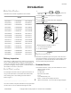
Introduction Introduction Model Identification 1.
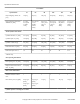
Specifications and Dimensions Specifications and Dimensions Specifications and Dimensions UW Models Specifications 35 60 80 100 125 150 Overall Dimensions Overall width, in. [mm] 33.4 [848] 36.6 [930] 41.5 [1054] 41.5 [1054] 48 [1219] 50.3 [1277] Overall height, in. [mm] 55.5 [1410] 64.5 [1638] 68.5 [1740] 68.5 [1740] 72 [1829] 79 [2007] Overall depth, in. [mm] 43.6 [1108] 45 [1143] 51.5 [1308] 54.
Specifications and Dimensions UW Models Specifications 35 60 80 100 125 150 Export shipping volume, ft3 [m3] 78 [2.2] 96 [2.7] 134 [3.8] 134 [3.80] 184 [5.3] 220 [6.3] Export shipping dimensions, WxDxH, in. [mm] 41 x 50 x 65.5 [1050 x 1280 x 1670] 43 x 52.125 x 74.5 [1092 x 1324 x 1892] 47 x 63.5 x 77.25 [1194 x 1613 x 1962] 47 x 63.5 x 77.25 [1194 x 1613 x 1962] 63.5 x 63 x 80 [1620 x 1610 x 2030] 61.5 x 71 x 87 [1562 x 1804 x 2210] Cylinder diameter, in. [mm] 26.
Specifications and Dimensions UW Models Specifications 35 60 80 100 125 150 1/2 Wash/reverse, RPM [G] [V-speed only] 26 [.25] 26 [.31] 26 [.35] 26 [.35] 26 [.40] 23 [.32] Wash/reverse, RPM [G] 42 [0.66] [UniLinc models] 40 [0.73] [Vspeed] 40 [0.8] 40 [0.8] 37 [0.8] 36 [0.8] 73 [2.57] [UniLinc models] 70 [2.5] 62 [2.29] 61 [2.29] 44 [0.73] [M30 Vspeed models] 44 [0.88] [2speed] 50 [0.95] [2speed] Distribution, RPM [G] [Vspeed only] 83 [2.57] 71 [2.3] 70 [2.
Specifications and Dimensions UW Models Specifications Vibration switch installed 35 60 STD [Vspeed] STD [Vspeed] N/A [2speed] N/A [2speed] 80 100 125 150 STD STD STD STD Direct Steam Heating [Optional] Steam inlet connection size, in. [mm] 0.5 [13] 0.5 [13] 0.5 [13] 0.5 [13] 0.75 [19] 0.75 [19] Number of steam inlets 1 1 1 1 1 1 Steam required to raise bath temperature 10°F, lbs. [10°C, kg] LOW 2.1 [1.7] 3.3 [2.7] 4.6 [3.7] 5.7 [4.6] 6.7 [5.4] 8.3 [6.7] MED 2.3 [1.
Specifications and Dimensions UW Models Specifications 35 60 80 100 125 150 N/A = Not Applicable Table 1 Machine Dimensions ment. Allow at least 6 inches [152 mm] between machines in multiple installations.
Specifications and Dimensions 1 2 3 6 4 5 F C A G B E D N M 9 7 L 10 K 11 14 P O 8 O J 13 12 H PHM858N_SVG 35-125 Pound Models 1. Door Unlock Button 2. Emergency Stop Button 3. Supply Dispenser 4. Door Handle 5. Spray Rinse Nozzle [Optional] 6. Recirculation Inlet 7. Water Inlet Valves 8. Steam Connection [Optional] 9. Shell Vent 10. Power Input [Electric Heat Models] 11. Power Input [Non-Electric Heat Models] 12. Drain [80, 100 and 125 models only] 13. Drain 14.
Specifications and Dimensions 1 8 2 9 10 3 6 4 7 F J 5 C A G E D B N M L 9 10 K 12 O P O 11 14 J H 13 PHM837N_SVG 150 Pound Model 1. Door Unlock Button 2. Emergency Stop Button 3. Supply Valve Box 4. Supply Dispenser 5. Spray Rinse Nozzle 6. Door Handle 7. Basket Jog Buttons 8. Recirculation Inlet 9. Shell Vent 10. Water Inlet Valves 11. Steam Connection [Optional] 12. Power Input 13. Drain 14.
Specifications and Dimensions Machine Dimensions [Refer Figure 2 and Figure 3 ] 35 60 80 100 125 150 A 30.1 in. [765 mm] 35.6 in. [905 mm] 41.1 in. [1045 mm] 41.1 in. [1045 mm] 48 in. [1219 mm] 50.3 in. [1277 mm] B 33.4 in. [848 mm] 36.6 in. [930 mm] 41.5 in. [1054 mm] 41.5 in. [1054 mm] 48 in. [1219 mm] 50.3 in. [1277 mm] C 23.8 in. [603 mm] 28.3 in. [718 mm] 29 in. [737 mm] 29 in. [737 mm] 29 in. [737 mm] 32 in. [813 mm] D 43.6 in. [1108 mm] 45 in. [1143 mm] 51.5 in.
Specifications and Dimensions Machine Dimensions [Refer Figure 2 and Figure 3 ] 35 P 2.9 in. [72 mm] 60 2.9 in. [72 mm] 80 100 2.9 in. [72 mm] 2.9 in. [72 mm] 125 2.9 in. [72 mm] 150 2.9 in. [72 mm] Table 2 Machine Foundation Requirements A 6 inch [153 mm] [for 35 and 60 2-speed, L-speed and M-speed models] or a 12 inch [305 mm] [for all other models] thickness of 4,000 psi reinforced concrete foundation is absolutely necessary because of the high extract speed and the G-forces exerted.
Specifications and Dimensions NOTE: If the washer-extractor installation will include the Premium Wet Clean Module, the elevated base must be designed to accommodate the additional depth of 24 inches [610 mm]. 7. Allow concrete to cure. 8. Proceed to Machine Mounting and Grouting section. C E A C G C D C 1 B F PHM838N_SVG 1. Compact Fill Figure 4 35 A 60 2-Speed, L-Speed and M-Speed 6 in. [152 mm] 80 100 125 150 12 in. [305 mm] 12 in. [305 mm] 12 in. [305 mm] 12 in.
Specifications and Dimensions 35 G 18 in. [457 mm] 60 18 in. [457 mm] 80 100 18 in. [457 mm] 125 18 in. [457 mm] 18 in. [457 mm] 150 18 in. [457 mm] Table 3 Floor Load Data Floor Load Data Specifications Static floor load, lbs. [kN] Static pressure, lbs.-ft2 [kN-m2] Dynamic floor load, lbs. [kN] Dynamic pressure, lbs.-ft2 [kNm2] F8423301ENR3 Speed 35 60 80 100 125 150 V-speed 1,272 [5.66] 1,442 [6.42] 2,292 [10.2] 2,490 [11.1] 3,283 [14.6] 3,936 [17.5] 2-speed 1,272 [5.
Specifications and Dimensions Floor Load Data Specifications Dynamic load frequency, Hz 1Maximum Speed 35 60 80 100 125 V-speed 15 13.6 12.8 12.8 9.7 11.7 2-speed 8.2 8.0 N/A N/A N/A N/A L-speed 8.63 7.82 N/A N/A N/A N/A M-speed 11.58 10.5 9.9 9.9 9.2 N/A V-speed 2,848 [12.7] 4,146 [18.4] 5,895 [26.2] 6,994 [31.1] 7,028 [31.3] 8,437 [37.52] 2-speed 1,745 [7.8] 2,392 [10.6] N/A N/A N/A N/A L-speed 1,797 [8] 2,342 [10.
Specifications and Dimensions the threaded end of the bolts should extend 3 inches [76 mm] above the mounting surface. Refer to Figure 5 for a typical installation of individual mounting bolts. A 1 B 2 3 C D 4 5 E PHM862N_SVG Acrylic Adhesive Anchors 1. Machine Frame Base 2. Grout 3. Acrylic Adhesive 4. Anchor Bolt [minimum Grade 5 SAE rating] 5. Concrete Figure 5 Acrylic Adhesive Anchors A 2 in. [64 mm] [minimum thread extension] B 3/4 in. [19 mm] C 6 in. [165 mm] D 4 in.
Specifications and Dimensions A E F B C B E G D E A PHM547N_SVG PHM574N_SVG 35 Pound 2-Speed Models 35 Pound V-Speed Models H H E J M E B I L K E N E PHM548N_SVG PHM575N_SVG 60 Pound 2-Speed Models 60 Pound V-Speed Models O T W Q P R S U E V E S E E PHM576N_SVG PHM192N_SVG 80 Pound Models 100 Pound Models DD X Y EE E AA FF Z CC BB E GG PHM180N_SVG 125 Pound Models GG PHM605N_SVG 150 Pound Models = GROUT PHM943N_SVG 22 © Copyright, Alliance Laundry Systems LLC
Specifications and Dimensions A 30.13 in. [765 mm] R 17.5 in. [445 mm] B 36 in. [914 mm] S 33 in. [838 mm] C 17.88 in. [454 mm] T 41.13 in. [1044 mm] D 20 in. [508 mm] U 43.81 in. [1113 mm] E 4.06 in. [103 mm] typical V 20.69 in. [526 mm] F 27.88 in. [708 mm] W 10.88 in. [276 mm] G 22 in. [559 mm] X 48 in. [1219 mm] H 35.63 in. [905 mm] Y 3.25 in. [83 mm] I 35.94 in. [913 mm] Z 48 in. [219 mm] J 11.94 in. [303 mm] AA 24.31 in. [617 mm] K 27.5 in. [699 mm] BB 39.
Specifications and Dimensions B C A E D G F I H K J J L 1 PHM630N_SVG 35 Pound Models 1. Front of Machine Figure 6 Mounting Bolt Hole Locations – 35 Pound Models A 36 in. [914 mm] B 28.63 in. [727 mm] C 0.75 in. [19 mm] D 43.28 in. [1089 mm] E 30.19 in.
Specifications and Dimensions Mounting Bolt Hole Locations – 35 Pound Models F 40.19 in. [1022 mm] G 34.5 in. [876 mm] H 34.16 in. [868 mm] I 21.19 in. [538 mm] J 2 in. [51 mm] K 26.13 in. [664 mm] L 30.13 in.
Specifications and Dimensions A A B D E C H F I I G J K L L M A N 1 PHM631N_SVG 60 Pound V-speed Models 1. Front of Machine Figure 7 Mounting Bolt Hole Locations – 60 Pound Models [V-speed] A 0.75 in. [19 mm] B 34.13 in. [867 mm] C 44.81 in. [1138 mm] D 4.81 in. [122 mm] E 9 in.
Specifications and Dimensions Mounting Bolt Hole Locations – 60 Pound Models [V-speed] F 1.25 in. [32 mm] G 39.25 in. [997 mm] H 10.75 in. [273 mm] I 36 in. [914 mm] J 34.56 in. [878 mm] K 10.69 in. [271 mm] L 2 in. [51 mm] M 31.63 in. [803 mm] N 35.63 in.
Specifications and Dimensions A B A A D G C E F H E I J A L K K M 1 PHM666N_SVG 60 Pound 2-speed Models 1. Front of Machine Figure 8 Mounting Bolt Hole Locations – 60 Pound Models [2-speed] A 0.75 in. [19 mm] B 34.13 in. [867 mm] C 46.81 in. [1189 mm] D 4.19 in. [122 mm] E 1.25 in. [32 mm] F 44.81 in.
Specifications and Dimensions Mounting Bolt Hole Locations – 60 Pound Models [2-speed] G 9 in. [229 mm] H 36 in. [914 mm] I 39.25 in. [997 mm] J 21.44 in. [554 mm] K 2 in. [51 mm] L 31.75 in. [803 mm] M 35.63 in.
Specifications and Dimensions A A B C D G E F H I K J H K L L M A 1 PHM632N_SVG 80 and 100 Pound Models 1. Front of Machine Figure 9 Mounting Bolt Hole Locations – 80 and 100 Pound Models A 0.75 in. [19 mm] B 39.63 in. [1008 mm] C 6.75 in. [171 mm] D 9 in.
Specifications and Dimensions Mounting Bolt Hole Locations – 80 and 100 Pound Models E 43.75 in. [1111 mm] F 2.25 in. [57 mm] G 52.19 in. [1326 mm] H 13.63 in. [346 mm] I 46.31 in. [1176 mm] J 39.75 in. [1010 mm] K 35.13 in. [892 mm] L 3 in. [76 mm] M 41.13 in.
Specifications and Dimensions A A B C D F E G H I J K K F 1 A PHM633N_SVG 125 Pound Models 1. Front of Machine Figure 10 Mounting Bolt Hole Locations – 125 Pound Models A 0.75 in. [19 mm] B 46.5 in. [1181 mm] C 7 in.
Specifications and Dimensions Mounting Bolt Hole Locations – 125 Pound Models D 10 in. [254 mm] E 61.5 in. [1562 mm] F 48 in. [1219 mm] G 55.47 in. [1409 mm] H 15 in. [381 mm] I 48.94 in. [1243 mm] J 15.25 in. [387 mm] K 23.25 in.
Specifications and Dimensions A B A D C E F G I H J K K L M 1 PHM778N_SVG 150 Pound Models 1. Front of Machine Figure 11 Mounting Bolt Hole Locations – 150 Pound Models A 10.38 in. [264 mm] B 48.13 in. [1223 mm] C 56 in. [1422 mm] D 51.38 in.
Specifications and Dimensions Mounting Bolt Hole Locations – 150 Pound Models E 47.88 in. [1216 mm] F 57.4 in. [1457 mm] G 12.13 in. [308 mm] H 15 in. [381 mm] I 67.1 in. [1704 mm] J 4 in. [102 mm] K 1.5 in. [38.1 mm] L 47 in. [1193 mm] M 50 in. [1270 mm] Table 12 Gap Setting for Vibration Switch After the machine has been properly installed, the vibration switch gap must be verified. To locate the vibration switch refer to Figure 12 , Figure 13 and Figure 14 .
Specifications and Dimensions 1 2 PHM794N_SVG 35 Pound Models 1. Adjustment Bolt 2. Vibration Switch Figure 12 1 2 PHM795N_SVG 60, 80, 100 and 125 Pound Models 1. Adjustment Bolt 2. Vibration Switch Figure 13 Verify Safety Switch Operation [150 Pound Design 2 Models]: Place a large magnet above the normally-closed ball switch to verify switch operation. Refer to Figure 14 .
Specifications and Dimensions IMPORTANT: UW150 Design 2 machines are manufactured with a normally-closed ball switch and should not require any adjustment. To avoid nuisance tripping, machine must be level with a summed value of 3/8 inch [ 9.5 mm] front to back and right to left to the earth. If switch is tripped, check if machine is level and then for poor grouting and broken anchor bolts. DO NOT BYPASS SAFETY SWITCH. Contact a qualified service technician for further assistance.
Specifications and Dimensions 1 3 2 2 1 9 3 4 4 5 6 A 8 5 7 7 6 8 PHM830N_SVG PHM829N_SVG Direct Drain System 1. Drain Pipe 2. Overflow Pipe (optional) 3. Vent 4. Trap (if required by local codes) 5. Steel Grate 6. Drain Trough 7. Strainer 8. Waste Line 9. 3 in. [76 mm] minimum gap Figure 15 All drain systems must be vented to prevent an air lock and to prevent siphoning. Drain Trough System 1. Rear of Machine 2. Drain Pipe 3. Overflow Pipe (optional) 4. Steel Grate 5. Drain Trough 6.
Specifications and Dimensions Drain Information Specifications 35 60 80 100 125 150 Drain connection size, I.D., in. [mm] with second drain: 2.375 [60] 3 [76] 3 [76] 3 [76] 3 [76] 3 [76] Number of drain outlets 1 1 2 [UniLinc] 2 [UniLinc] 2 [UniLinc] 2 1 [M30] 1 [M30] 1 [M30] Drain flow capacity, gal/ min. [l/min.
Specifications and Dimensions Maximum water inlet temperature is 190 °Fahrenheit [ 88 °Celsius]. WARNING To prevent personal injury, avoid contact with inlet water temperatures higher than 125° Fahrenheit [51° Celsius] and hot surfaces. W748 Water Supply Information Specifications 35 60 80/100 125/150 Number of main fill water inlets 2 2 2 2 Main fill water inlet size at machine, in. [mm] 3/4 3/4 3/4 1 Factory supplied hose Size 19 19 19 25.4 Thread 11.5 11.5 11.
Specifications and Dimensions Water Supply Line Sizing 1 2 Supply Line Size, in. [mm] Model Number of Machines Main Hot/Cold 3 4 100 5 3 2 [51] 1.5 [38] 4 2.5 [64] 2 [51] 1 1.5 [38] 1 [25] 2 2 [51] 1.5 [38] 3 2 [51] 1.5 [38] 4 2.5 [64] 2 [51] 1 2 [51] 1.25 [32] 2 2.5 [64] 2 [51] 3 2.5 [64] 2 [51] 4 2.5 [64] 2.5 [64] 1 2 [51] 1.25 [32] PHM831N_SVG 1. 2. 3. 4. 5.
Specifications and Dimensions WARNING Electrical shock hazard will result in death or serious injury. Disconnect electric power and wait three (3) minutes before servicing. PHM756N_SVG N, P and R–voltage Models W784 On V-speed models, the AC inverter drive requires a clean power supply free from voltage spikes and surges. Use a voltage monitor to check incoming power. WARNING Dangerous voltages are present inside the machine. Only qualified personnel should attempt adjustments and troubleshooting.
Specifications and Dimensions For personal safety and for proper operation, the machine must be grounded in accordance with state and local codes or accepted European standards. The ground connection must be made to a proven earth ground, not to conduit or water pipes. Refer to Figure 20 and Figure 21 . 1 SERVICE GROUND 2 CHASIS L1 L2 2 L1 L3 L2 1 TB1 PHM721N_SVG L3 SERVICE GROUND Machines without Electric Heat 1. Grounding Lug: Connect to proven earth ground 2.
Specifications and Dimensions 35 Pound Capacity Models Voltage Designation Code N (Starting 7/7/10) Voltage Standard 440-480 Specifications Cycle 50/60 Phase 3 Wire 3 Electric Heat P (Starting 7/7/10) Standard 380-415 50/60 3 Full Load Amps 3 Electric Heat Breaker AWG mm2 6 15 14 2.5 23 30 10 6 6 15 14 2.5 23 30 10 6 NOTE: Wire sizing listed in these tables is based on Article 310, Table 310.16 of the NEC; at 104°F [40°C] ambient temperature.
Specifications and Dimensions 60 Pound Capacity Models Voltage Designation Code R (Through 7/6/10) Voltage Standard 380–480 Specifications Cycle 50/60 Phase 3 Wire 3 Electric Heat N (Starting 7/7/10) Standard 440-480 50/60 3 3 Electric Heat P (Starting 7/7/10) Standard 380-415 50/60 3 Full Load Amps 3 Electric Heat Breaker AWG mm2 7 15 14 2.5 37 40 8 10 7 15 14 2.5 37 40 8 10 7 15 14 2.
Specifications and Dimensions 80 Pound Capacity Models Voltage Designation Code Q (Starting 4/14/10) Voltage Standard 208–240 Specifications Cycle 50/60 Phase 3 Wire 3 Electric Heat R (Through 7/6/10) Standard 380–480 50/60 3 3 Electric Heat N (Starting 7/7/10) Standard 440-480 50/60 3 3 Electric Heat P (Starting 7/7/10) Standard 380-415 50/60 3 Electric Heat 3 Full Load Amps Breaker AWG mm2 14 20 12 4 105 110 1 50 10 15 14 2.5 39 40 8 10 10 15 14 2.
Specifications and Dimensions 100 Pound Capacity Models Voltage Designation Code Q (Through 4/13/10) Voltage Standard 200–240 Specifications Cycle 50/60 Phase 3 Wire 3 Electric Heat Q (Starting 4/14/10) Standard 208–240 50/60 3 3 Electric Heat R (Through 7/6/10) Standard 380–480 50/60 3 3 Electric Heat N (Starting 7/7/10) Standard 440-480 50/60 3 3 Electric Heat P (Starting 7/7/10) Standard 380-415 50/60 3 Electric Heat 3 Full Load Amps Breaker AWG mm2 10 15 14 2.
Specifications and Dimensions 125 Pound Capacity Models Voltage Designation Code Voltage Specifications Cycle Phase Full Load Amps Wire Breaker AWG mm2 Q 200–240 50/60 3 3 12 15 14 2.5 R (Through 7/6/10) 380–480 50/60 3 3 8 15 14 2.5 N (Starting 7/7/10) 440-480 50/60 3 3 8 15 14 2.5 74 80 4 25 8 15 14 2.
Specifications and Dimensions 150 Pound Capacity Models Voltage Designation Code Voltage Specifications Cycle Phase Wire Full Load Amps Breaker AWG mm2 NOTE: Wire sizing listed in these tables is based on Article 310, Table 310.16 of the NEC; at 104°F [40°C] ambient temperature. Follow your local electrical codes. Use only copper conductors, rated for 194°F [90ºC] or higher, type THHN or better. No more than three current carrying conductors per raceway.
Specifications and Dimensions 60 Pound Capacity Models Voltage Designation Code Voltage X Q Standard Specifications Cycle Phase Wire Full Load Amps Breaker mm2 200–240 50/60 1/3 2/3 17/11 20/16 2.5 200–240 50/60 3 3 11 16 2.5 71 80 16 Electric Heat O** 208–240 60 3 3 26 32 2.5 N 440–480 50/60 3 3 37 40 4 380-415 50/60 3 3 7 10 2.5 37 40 4 P Standard Electric Heat NOTE: Follow your local electrical codes.
Specifications and Dimensions 80 Pound Capacity Models Voltage Designation Code N Voltage Standard 440-480 Specifications Cycle 50/60 Phase 3 Wire 3 Electric Heat P Standard 380-415 50/60 3 3 Electric Heat Full Load Amps Breaker mm2 11 16 2.5 39 40 4 11 16 2.5 39 40 4 NOTE: Follow your local electrical codes. Use only copper conductors, rated for 194°F [90ºC] or higher, type THHN or better. No more than three current carrying conductors per raceway.
Specifications and Dimensions 100 Pound Capacity Models Voltage Designation Code Voltage Specifications Cycle Phase Wire Full Load Amps Breaker mm2 NOTE: Follow your local electrical codes. Use only copper conductors, rated for 194°F [90ºC] or higher, type THHN or better. No more than three current carrying conductors per raceway. Contact your local Authority having jurisdiction if you have questions. Circuit breakers should be UL 489 listed or better.
Specifications and Dimensions 150 Pound Capacity Models Voltage Designation Code Voltage Specifications Cycle Phase Wire Full Load Amps Breaker mm2 Q 200–240 50/60 3 3 17 20 2.5 N 440-480 50/60 3 3 11 16 2.5 P 380-415 50/60 3 3 11 16 2.5 NOTE: Follow your local electrical codes. Use only copper conductors, rated for 194°F [90ºC] or higher, type THHN or better. No more than three current carrying conductors per raceway.
Specifications and Dimensions Steam Supply Information Capacities Maximum pressure, psi [bar] 35 60 80 [5.5] 80 80 [5.5] 80 [5.5] 100 80 [5.5] 125/150 80 [5.5] Table 29 IMPORTANT: Failure to install the customer supplied steam filter may void the warranty. Chemical Injection Supply System WARNING IMPORTANT: Undiluted chemical dripping can damage the machine. All chemical injection supply dispenser pumps and dispenser tubing should be mounted below the machine’s injection point.
Specifications and Dimensions Connecting External Liquid Supplies 1. Remove knockout from supply dispenser. Refer to Figure 23 . Plugs are assembled inside the tubing ring. 2. Install strain relief connector in hole with strain reliefs, included in the seal nut. 3. Insert tubes through base. Do not remove cups. Tube should extend into the plastic cup, with the exception of the softener tube, which should be routed to the outside of the cup. 4.
Specifications and Dimensions 1 2 3 12 4 5 6 7 8 9 10 11 PHM832N_SVG 1. Strain Relief for Liquid Chemical Supply Lines 2. Seal Nut 3. Supply Dispenser Lid 4. Tubing Ring 5. Base 6. Nozzles 7. Tubing 8. Nut 9. Dry Supply Cups 10. Dry Supply Insert 11. Polypropylene Supply Dispenser 12. Knockout IMPORTANT: Do not attach anything to nozzles. Air gap must be maintained.
Specifications and Dimensions 1 2 3 4 5 6 PHM553N_SVG IMPORTANT: Do not attach anything to nozzles. Air gap must be maintained. Five Compartment Supply Dispenser (Optional) 1. Strain Relief for Liquid Chemical Supply Lines 2. Supply Dispenser Lid 3. Nozzles 4. Dry Supply Cups 5. Dry Supply Insert 6. Polypropylene Supply Dispenser Figure 24 1. Remove knockout from supply dispenser. Refer to Figure 24 . Plugs are assembled inside the tubing ring. 2.
Specifications and Dimensions Do not attempt to make chemical injection electrical connections to points other than those provided specifically for that purpose by the factory. 2 3 1 4 PHM940N_SVG * Use a check valve on the end of tubing † Must be mounted below the injection point 1. 2. 3. 4.
Specifications and Dimensions Chemical Injection Using Internal 24VAC Control Transformer • NOTE: Using the Internal 24VAC 300 Milliamp Control Transformer is recommended by Alliance Laundry Systems. • IMPORTANT: DO NOT remove the red jumper wire from the terminal strip. There are 3 terminals necessary for this connection option. Terminal “24VAC COM” is used to connect one side of the internal control transformer to the external dispenser input signals common.
Specifications and Dimensions 3 1 4 2 = Neutral = Power 5 PHM823N_SVG 1. 2. 3. 4. 5. External Supply Power Output Red Jumper Wire External Supply Input Signal Common VAC Power Terminal VAC RETURN Terminal Figure 28 External Supply Signals CAUTION Do not attempt to increase fuse rating or alter wiring of external chemical supply terminal strip in such as way that may conflict with the suggested methods provided on the Optional External Supply Wiring Diagram.
Specifications and Dimensions 3 = Neutral = Power 1 2 PHM822N_SVG 1. ES1 Power supply 2. K1 Contact 3. Supply 1 Signal Figure 29 3 = Neutral = Power 1 2 PHM824N_SVG 1. ES1 Power supply 2. K1 Contact 3.
Startup Startup Basket Rotation After installation is complete, run the machine through a test cycle and check for a clockwise basket rotation during the extract step. 1. If rotation is not clockwise, disconnect the power from the machine. 2. Have a qualified electrician reverse any 2 motor leads.
Operation Operation Operating Instructions for UniLinc Control 1. Verify display shows the Cycle Menu Screen. 2. Press the door unlock button located on the lower left front on the control. Refer to Figure 31 . 1 PHM705N_SVG UW35–UW150 Models 1. Emergency Stop Button PHM717N_SVG UW150 Models Figure 31 NOTE: Door must be opened within 5 seconds of pressing the door unlock button. 3. 35 – 125 models: Turn door handle clockwise and swing the door left to open. Refer to Figure 32 . Figure 33 4.
Operation 6. Add dry supplies to the supply dispenser compartment cups prior to the start of each cycle. Liquid supplies can be injected directly into the supply dispenser by an external chemical supply system. NOTE: Supply dispenser compartment cups must not be removed when an external chemical injection supply system is attached to the machine. 7. Press and keypads to select desired wash cycle.
Operation PHM791N_SVG PHM622N_SVG Figure 39 Figure 37 The jog feature is deactivated when the loading door is closed and the jog buttons are not pressed. 4. Load to capacity whenever possible. DO NOT OVERLOAD. Underloading can cause out-of-balance conditions that can shorten machine life. WARNING To avoid personal injury, do NOT reach into the basket while it is rotating. Keep all personnel at a safe distance from the machine while using the Basket Jog Feature.
Operation 7. Press the numeric keypads to select the desired wash cycle. Refer to Cycle Number .
Operation Shakeout Routine WARNING NEVER insert hands or objects into basket until it has completely stopped. Doing so could result in serious injury. SW012 A shakeout agitation step is programmed at the end of every cycle and will help prevent tangling of the load. The shakeout time is set at the factory to agitate for 20 seconds. Models Equipped with Both Steam and Electric Heating 1. To switch between the heating type, locate the switch on the left side of control module. Refer to Figure 41 . 2.
Maintenance Maintenance Maintenance The following maintenance procedures must be performed regularly at the required intervals. Routine maintenance maximizes operating efficiency and minimizes downtime. The maintenance procedures described below will prolong the life of the machine and help prevent accidents. Daily WARNING WARNING Sharp edges can cause personal injury. Wear safety glasses and gloves, use proper tools and provide lighting when handling sheet metal parts.
Maintenance End of Day • 1. Clean the AC drive filter (where applicable): a. Remove the external plastic cover which contains the filter. b. Remove the foam filter from the cover. c. Wash the filter with warm water and allow to air dry. Filter can be vacuumed clean. • IMPORTANT: The control module cover and fan filter must be in place for the fan to properly cool the AC inverter drive. Failure to observe this warning will void the warranty and could lead to expensive AC inverter drive repair. 2.
Maintenance • 1 2 3 4 5 P045I_SVG 1. 2. 3. 4. 5. Drive Motor Drive Pulley Belt Straightedge Driven Pulley Figure 44 4. Check overflow hose and drain hose for leaks or visible signs of deterioration. Replace immediately if either are present. 5. Clean inlet hose filter screens: a. Turn water off and allow valve to cool, if necessary. b. Unscrew inlet hose and remove filter screen. c. Clean with soapy water and reinstall. Replace if worn or damaged. 6. Tighten anchor bolts, if necessary. 7.
Disposal of Unit Disposal of Unit Disposal of Unit This appliance is marked according to the European directive 2002/96/EC on Waste Electrical and Electronic Equipment (WEEE). This symbol on the product or on its packaging indicates that this product shall not be treated as household waste. Refer to Figure 45 . Instead it shall be handed over to the applicable collection point for the recycling of electrical and electronic equipment.