Basic Installation/Operation Washer-Extractors Pocket Hardmount P005I Keep These Instructions for Future Reference. (If this machine changes ownership, this manual must accompany machine.) www.comlaundry.com Part No.
Basic Installation/Operation Table of Contents Safety Information.............................................................................. Explanation of Safety Messages........................................................... Important Safety Instructions ............................................................... Safety Decals ........................................................................................ Operator Safety................................................................
Basic Installation/Operation Safety Information Explanation of Safety Messages Precautionary statements (“DANGER,” “WARNING,” and “CAUTION”), followed by specific instructions, are found in this manual and on machine decals. These precautions are intended for the personal safety of the operator, user, servicer, and those maintaining the machine.
Basic Installation/Operation 9. Do not install or store the washer where it will be exposed to water and/or weather. 10. Do not tamper with the controls. 11. Do not repair or replace any part of the washer, or attempt any servicing unless specifically recommended in the user-maintenance instructions or in published user-repair instructions that the user understands and has the skills to carry out. 12.
Basic Installation/Operation WARNING CAUTION This machine must be installed, adjusted, and serviced by qualified electrical maintenance personnel familiar with the construction and operation of this type of machinery. They must also be familiar with the potential hazards involved. Failure to observe this warning may result in personal injury and/or equipment damage, and may void the warranty. SW004 IMPORTANT: Ensure that the recommended clearances for inspection and maintenance are provided.
Basic Installation/Operation Operator Safety Do not bypass any safety devices in the machine. WARNING WARNING NEVER insert hands or objects into basket until it has completely stopped. Doing so could result in serious injury. SW012 To ensure the safety of machine operators, the following maintenance checks must be performed daily: Never operate the machine with a bypassed or disconnected balance system.
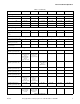
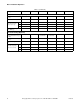
Basic Installation/Operation Installation General Specifications UW UniLinc and M30 Control Models Refer to Table 1. . Specifications 35 60 80 100 125 150 Overall width, in (mm) 33.375 (848) (Models through 5/31/09) 32.5 (826) (Models starting 6/1/09) 36.625 (930) 41.5 (1054) 41.5 (1054) 48 (1219) 50.25 (1277) Overall height, in (mm) 55.5 (1410) 64.5 (1638) 68.5 (1740) 68.5 (1740) 72 (1829) 79 (2007) Overall depth, in (mm) 43.625 (1108) (Variable-speed models through 5/31/09) 38.
Basic Installation/Operation Table 1 (continued) Specifications 35 60 80 100 125 150 Cylinder diameter, in (mm) 26.25 (667) 32 (813) 36 (914) 36 (914) 42 (1067) 43 (1093) Cylinder depth, in (mm) 18.375 (467) 20 (508) 21 (533) 27 (686) 24 (610) 27.8125 (706) Cylinder volume, ft3 (l) 5.76 (163) 9.31 (264) 12.4 (350) 15.9 (450) 19.2 (544) 23.4 (662) Perforation size, in (mm) 0.1875 (4.8) 0.1875 (4.8) 0.1875 (4.8) 0.1875 (4.8) 0.1875 (4.8) 0.1875 (4.
Basic Installation/Operation Table 1 (continued) Specifications 35 60 80 100 125 150 0.5 (13) 0.5 (13) 0.5 (13) 0.5 (13) 0.75 (19) 0.75 (19) 1 1 1 1 1 1 LOW 2.1 (1.5) 3.3 (2.4) 4.6 (3.3) 5.7 (4.1) 6.7 (4.9) 8.3 (6.0) MED 2.3 (1.7) 3.7 (2.6) 5.2 (3.8) 6.5 (4.7) 7.8 (5.6) 9.5 (6.9) HIGH 2.7 (1.9) 4.1 (2.9) 6.1 (4.4) 7.6 (5.5) 9.1 (6.6) 11.1 (8.0) 1.4 (21.4) 2.1 (33.4) 3.1 (48.4) 3.8 (60.4) 4.6 (72.0) 5.8 (91.0) 15.6 27.4 41.2 (Q-Volt) 27.4 (N-Volt) 41.
Basic Installation/Operation UW A-Control, Variable-Speed Models . Refer to Table 2. UWAV Pocket Hardmount General Specifications Specifications 35 60 80 100 125 Overall width, in. (mm) 32.5 (826) 36.625 (930) 41.5 (1054) 41.5 (1054) 48 (1219) Overall height, in. (mm) 55.5 (1410) 64.5 (1638) 65.5 (1740) 68.5 (1740) 72 (1829) Overall depth, in. (mm) 43.625 (1108) 45 (1143) 51.5 (1308) 54.5 (1384) 58 (1473) Overall Dimensions Weight and Shipping Information Net weight, lb.
Basic Installation/Operation Table 2 (continued) UWAV Pocket Hardmount General Specifications Specifications 35 60 80 100 125 Drive Train Information Number of motors in drive train Drive motor power, hp (kW) 1 1 1 1 1 2.3 (1.7) 2.9 (2.2) 5.0 (3.7) 5.0 (3.7) 7.5 (5.6) 26 / .31 26 / .35 26 / .35 26 / .40 Cylinder Speeds / Centrifugal Force Data 1/2 Wash/reverse, RPM / g 26 / .25 Wash/reverse, RPM / g 42 / .66 40 / .73 40 / .82 40 / .82 37 / .82 Distribution, RPM / g 83 / 2.
Basic Installation/Operation UW P-Control, Variable-Speed Models . Refer to Table 3. UWPV Models Specifications 35 60 80 100 125 150 Overall width, in. (mm) 32.5 (826) 36.63 (930) 41.5 (1054) 41.5 (1054) 48 (1219) 50.25 (1277) Overall height, in. (mm) 55.5 (1410) 64.5 (1638) 68.5 (1740) 68.5 (1740) 72 (1829) 79 (2007) Overall depth, in. (mm) 43.63 (1108) 45 (1143) 51.5 (1308) 54.5 (1384) 58 (1473) 63 (1600) Overall Dimensions Weight And Shipping Information Net weight, lb.
Basic Installation/Operation Table 3 (continued) UWPV Models Specifications 35 60 80 100 125 150 26 / .31 26 / .35 26 / .35 26 / .40 23 / .31 Cylinder Speeds / Centrifugal Force Data 1/2 Wash/reverse, RPM / g 26 / .25 Wash/reverse, RPM / g 42 / .66 40 / .73 40 / .82 40 / .82 37 / .82 36 / 0.8 Distribution, RPM / g 83 / 2.57 71 / 2.29 73 / 2.57 70 / 2.50 62 / 2.29 61 / 2.
Basic Installation/Operation UW 2 Speed Models with P-Control, S-Control, Mechanical Timer or B-Control . Refer to Table 4. UW 2 Speed Models UW35 UW60 Overall Dimensions Overall width, in. (mm) 32-1/2 (826) 36-5/8 (930) Overall height, in. (mm) 55-1/2 (1410) 64-1/2 (1638) Overall depth, in. (mm) 38-1/4 (972) 45 (1143) 750 (341) 1136 (515) Weight and Shipping Information Net weight, lb. (kg) Basket/shaft weight, lb. (kg) Domestic shipping weight, lb. (kg) Domestic shipping volume, ft.
Basic Installation/Operation Table 4 (continued) UW 2 Speed Models UW35 UW60 1 1 Wash/reverse motor power, HP (kW) 0.4 (0.3) 0.6 (0.5) High extract motor power, HP (kW) 1.8 (1.3) 3.0 (2.2) Wash/reverse speed, RPM / g 50 / 0.95 44 / 0.
Basic Installation/Operation UW 3 Speed Models with P-Control or S-Control Refer to Table 5. UW 3 Speed Models UW35 UW60 Overall Dimensions Overall width, in. (mm) 32-1/2 (826) 36-5/8 (930) Overall height, in. (mm) 55-1/2 (1410) 64-1/2 (1638) Overall depth, in. (mm) 36-3/4 (933) 45 (1143) 750 (341) 557 (1229) Weight and Shipping Information Net weight, lb. (kg) Basket/shaft weight, lb. (kg) Domestic shipping weight, lb. (kg) Domestic shipping volume, ft.
Basic Installation/Operation Table 5 (continued) UW 3 Speed Models UW35 UW60 Average power used per cycle, kWh 0.24 0.47 Max nominal sound emission, dBA 72 81 625 (157) 875 (220) 2 2 Wash/reverse motor power, hp (kW) 0.4 (0.3) 0.9 (0.7) Distribution motor power, hp (kW) 0.45 (0.34) 1.0 (0.8) High extract motor power, hp (kW) 3 (2.2) 3.5 (2.6) 45 / 0.76 42 / 0.
Basic Installation/Operation UniLinc and M30 Control Models WARNING Dimensional Clearances Crush hazard. Allow a minimum of 24 inches (60 cm) at the rear and 6 inches (45 cm) at the sides for maintenance, inspection, and adjustment. Allow at least 6 inches (45 cm) between machines in multiple installations. Machine dimensions are indicated in Table 6 and specified in Figure 1 and Figure 2.
Basic Installation/Operation 3 2 3 4 8 5 1 6 7 F E C G (BASE) D (OVERALL) A (BASE) B (OVERALL) 10 L 11 9 M 12 Q 13 16 K N P O J 15 14 H 35 - 125 PHM770N 1 2 3 4 5 6 7 8 External Supply Control Mounting Bracket (Models through 6/30/08) Door Unlock Button Supply Valve Box Emergency Stop Button Supply Dispenser (optional) Door Handle Spray Rinse Nozzle (optional) Recirculation Inlet 9 10 11 12 13 14 15 16 Water Inlet Valves Steam Connection (Optional) Shell Vent Power Input (Electric
Basic Installation/Operation 2 3 9 4 1 10 11 5 7 8 F J 6 C G (BASE) A (BASE) E D (OVERALL) B (OVERALL) L 12 M 10 Q 13 K 11 15 N P O J H 14 UW150TV TMB736N PHM736N 1 2 3 4 5 6 7 External Supply Control Mounting Bracket (Models through 6/30/08) Door Unlock Button Emergency Stop Button Supply Valve Box Supply Dispenser Spray Rinse Nozzle Door Handle 8 9 10 11 12 13 14 15 Basket Jog Buttons Recirculation Inlet Shell Vent Water Inlet Valves Steam Connection (Optional) Power Input D
Basic Installation/Operation UWAV Models Dimensional Clearances Allow a minimum of 24 inches (60 cm) at the rear and 18 inches (45 cm) at the sides for maintenance, inspection, and adjustment. Allow at least 18 inches (45 cm) between machines in multiple installations. Machine dimensions are indicated in Figure 3 and specified in Table 7. NOTE: The dimensions shown here are for planning purposes only. They are approximate and subject to normal manufacturing tolerances.
Basic Installation/Operation 1 2 1 2 3 4 5 6 < < 3 F E C G (BASE) A (BASE) B (OVERALL) D (OVERALL) 4 5 6 7 I H Models UW 35 – 125 PHM623N 1 2 3 4 Supply Valve Box Supply Dispenser Door Handle Water Inlet Valve 5 6 7 Power Input Area (Inside) Steam Connector (Optional) Drain Figure 3 F232156 © Copyright, Alliance Laundry Systems LLC – DO NOT COPY or TRANSMIT 21
Basic Installation/Operation UWPV Models Dimensional Clearances Allow a minimum of 24 inches (60 cm) at the rear and 18 inches (45 cm) at the sides for maintenance, inspection and adjustment. Allow at least 18 inches (45 cm) between machines in multiple installations. Machine dimensions are indicated in Figure 4 and specified in Table 8. NOTE: The dimensions shown here are for planning purposes only. They are approximate and subject to normal manufacturing tolerances.
Basic Installation/Operation 1 5 2 3 4 F E C G (BASE) A (BASE) B (OVERALL) D (OVERALL) 11 6 7 8 I 10 9 H PHM387N UW35PV – UW125PV PHM387N 1 2 3 4 5 6 Supply Valve Box Supply Dispenser Door Handle Spray Rinse Nozzle Recirculation Inlet Premium Wet Clean Module (Optional) 7 8 9 10 11 Power Input Area (Inside) Steam Connection (Optional) Premium Wet Clean Module (Optional) Drain Water Inlet Valves Figure 4 F232156 © Copyright, Alliance Laundry Systems LLC – DO NOT COPY or TRANSMIT 23
Basic Installation/Operation 1 5 6 1 2 3 4 5 6 7 8 9 1 0 5 4 3 2 1 2 4 F I 3 C A (BASE) G (BASE) 7 D (OVERALL) B (OVERALL) E 8 H 9 UW150PV PHM603N 1 2 3 4 5 Supply Valve Box Supply Dispenser Spray Rinse Nozzle Door Handle Recirculation Inlet 6 7 8 9 Water Inlet Valves Power Input Area (Inside) Steam Connection (Optional) Drain Figure 5 24 © Copyright, Alliance Laundry Systems LLC – DO NOT COPY or TRANSMIT F232156
Basic Installation/Operation UW 2 Speed Models with P-Control, S-Control, Mechanical Timer or B-Control UW 2 Speed Machine Dimensions (Refer to Figure 6) Dimensions Dimensional Clearances Allow a minimum of 24 inches (60 cm) at the rear, and 18 inches (45 cm) at the sides for maintenance, inspection and adjustment. Allow at least 18 inches (45 cm) between machines in multiple installations. Machine dimensions are indicated in Figure 6 and specified in Table 9.
Basic Installation/Operation 1 2 3 4 F E E C A (BASE) G (BASE) B (OVERALL) D (OVERALL) 5 6 7 I 8 H PHM388N UW 2 Speed Models P032I 1 2 3 4 Supply Valve Box Supply Dispenser Door Handle Spray Rinse Nozzle (2 Speed, P-Control Models Only) 5 6 7 8 Water Inlet Valves Power Input Area (Inside) Steam Connection (Optional) Drain Figure 6 26 © Copyright, Alliance Laundry Systems LLC – DO NOT COPY or TRANSMIT F232156
Basic Installation/Operation UW 3 Speed Models with P-Control or S-Control UW 3 Speed Machine Dimensions (Refer to Figure 7) Dimensions Dimensional Clearances Allow a minimum of 24 inches (60 cm) at the rear and 18 inches (45 cm) at the sides for maintenance, inspection, and adjustment. Allow at least 18 inches (45 cm) between machines in multiple installations. Machine dimensions are indicated in Figure 7 and specified in Table 10. NOTE: The dimensions shown here are for planning purposes only.
Basic Installation/Operation 1 2 3 4 F E C G (BASE) A (BASE) D (OVERALL) B (OVERALL) 6 5 7 8 I H P032I UW 3 Speed Models P032I 1 2 3 4 Supply Valve Box Supply Dispenser Door Handle Spray Rinse Nozzle 5 6 7 8 Steam Connection (Optional) Water Inlet Valves Power Input Area (Inside) Drain Figure 7 28 © Copyright, Alliance Laundry Systems LLC – DO NOT COPY or TRANSMIT F232156
Basic Installation/Operation Operation UW Models With UniLinc Control 1. When display shows the Cycle Menu Screen washer-extractor is ready to be loaded with laundry. unlock button. Refer to Figure 10. 150 MODELS 2. On UW35-UW150 models. Press the door unlock button located on the lower left front on the control. Refer to Figure 8. 3. Open door within five seconds of pressing the door unlock keypad. UW35 – UW150 MODELS PHM717N PHM705N PHM705N Figure 8 4.
Basic Installation/Operation As the cycle proceeds, the display will show a summary of the cycle occurring. Refer to Figure 8 CAUTION Be careful around the open door, particularly when loading from a level below the door. Impact with door edges can cause personal injury. SW025 NOTE: When washing items which may disintegrate or fragment, such as mop heads or sponges, use laundry nets to prevent drain blockage.
Basic Installation/Operation UW Models With M30 Control 1. When display shows a cycle number, the washerextractor is ready to be loaded with laundry. 2. Press the STOP/UNLOCK button located on the control. Refer to Figure 14. 5. Load the washer-extractor to full capacity whenever possible, but do not exceed the rated dry-weight capacity of the machine if the fabric to be washed is quite dense, closely woven, and heavily soiled. Overloading can result in an inferior wash.
Basic Installation/Operation CAUTION Be careful around the open door, particularly when loading from a level below the door. Impact with door edges can cause personal injury. SW025 NOTE: When washing items which may disintegrate or fragment, such as mop heads or sponges, use laundry nets to prevent drain blockage. IMPORTANT: To prevent out-of-balance conditions, premature wear or damage to machine when using laundry nets, use several small nets in a load. 6.
Basic Installation/Operation Models Equipped with Both Steam and Electric Heating (UniLinc and M30 Controls) 1. To switch between the heating type, locate the switch on the left side of control module. Refer to Figure 17. 2. To select steam heat, make sure the switch is in the down position. OR To select electric heat, make sure the switch is in the up position.
Basic Installation/Operation UW Models with S-Control 4. Load the machine to full capacity whenever possible. DO NOT OVERLOAD. 1. Turn on the main power source (circuit breaker or cut-off switch on the wall). 2. Use left hand to press and hold the Door Unlock button located on the lower right front of the control panel. Refer to Figure 18. WARNING MACHINE MAY BE HOT AND CAUSE BURNS ATTEMPT NO ENTRY UNTIL BASKET HAS STOPPED SERIOUS INJURY MAY RESULT PHM590N Figure 20 CAUTION MD003J Figure 18 3.
Basic Installation/Operation 6. Add dry supplies to the supply dispenser compartment cups prior to the start of each cycle. Liquid supplies can be injected directly into the supply dispenser by an external chemical supply system. NOTE: Supply dispenser compartment cups must not be removed when an external chemical injection supply system is attached to the washerextractor. NOTE: Press keypads at their centers just hard enough to activate them. 8. Cycle is complete when display reads “donE”.
Basic Installation/Operation UW Models with P-Control WARNING Pre-Operating Instructions 1. Turn on the main power source (circuit breaker or cut-off switch on wall). Models with the rotation sensor will display WE-6 Firmware ID Code “HRWC18” and later (i.e., “HRWC19”) after power up. For models without rotation sensor, proceed to step 1 of Operating Instructions. 2. Display shows size of machine and will flash “TEST?” and “SPEED” for 15 seconds. 3. Push Start keypad during the 15 seconds.
Basic Installation/Operation 4. On UW150 models, use left hand to press and hold the door unlock button located on the door box. Refer to Figure 23. UW150 MODELS 6. Load the washer-extractor to full capacity whenever possible, but do not exceed the rated dry-weight capacity of the machine if the fabric to be washed is quite dense, closely woven, and heavily soiled. Overloading can result in an inferior wash.
Basic Installation/Operation CAUTION Be careful around the open door, particularly when loading from a level below the door. Impact with door edges can cause personal injury. SW025 NOTE: When washing items which may disintegrate or fragment, such as mop heads or sponges, use laundry nets to prevent drain blockage. IMPORTANT: To prevent out-of-balance conditions, premature wear or damage to machine when using laundry nets, use several small nets in a load. 7.
Basic Installation/Operation UW Models with A-Control 1. When display shows “Cyxx,” washer-extractor is ready to be loaded with laundry. 2. Use left hand to press and hold the door unlock button located on the lower right front of the control panel. Refer to Figure 25. 1 2 3 4 5 6 4. Load the washer-extractor to full capacity whenever possible, but do not exceed the rated dry-weight capacity of the machine if the fabric to be washed is quite dense, closely woven, and heavily soiled.
Basic Installation/Operation Liquid supplies can be injected directly into the supply dispenser by an external chemical supply system. CAUTION Be careful around the open door, particularly when loading from a level below the door. Impact with door edges can cause personal injury. NOTE: Supply dispenser compartment cups must not be removed when an external chemical injection supply system is attached to the washerextractor.
Basic Installation/Operation UW Models with B-Control 1. When display shows “----,” washer-extractor is ready to be loaded with laundry. 2. Use left hand to press and hold the door unlock button located on the lower right front of the control panel. Refer to Figure 28. 4. Load the washer-extractor to full capacity whenever possible, but do not exceed the rated dry-weight capacity of the machine if the fabric to be washed is quite dense, closely woven, and heavily soiled.
Basic Installation/Operation CAUTION Be careful around the open door, particularly when loading from a level below the door. Impact with door edges can cause personal injury. SW025 NOTE: When washing items which may disintegrate or fragment, such as mop heads or sponges, use laundry nets to prevent drain blockage. IMPORTANT: To prevent out-of-balance conditions, premature wear or damage to machine when using laundry nets, use several small nets in a load. 5.
Basic Installation/Operation Disposal of Unit This appliance is marked according to the European directive 2002/96/EC on Waste Electrical and Electronic Equipment (WEEE). This symbol on the product or on its packaging indicates that this product shall not be treated as household waste. Refer to Figure 31. Instead it shall be handed over to the applicable collection point for the recycling of electrical and electronic equipment.