Installation/Operation Frontload Washers Metered Commercial FLW1527C Keep These Instructions for Future Reference. (If this machine changes ownership, this manual must accompany machine.) www.comlaundry.com Part No.
WARNING Failure to install, maintain, and/or operate this machine according to the manufacturer's instructions may result in conditions which can produce bodily injury and/or property damage. W030 NOTE: The WARNING and IMPORTANT instructions appearing in this manual are not meant to cover all possible conditions and situations that may occur. It must be understood that common sense, caution, and carefulness are factors which cannot be built into these washers.
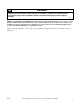
Table of Contents Safety Information.............................................................................. Explanation of Safety Messages........................................................... Important Safety Instructions ............................................................... 3 3 3 Installation........................................................................................... Dimensions and Specifications.............................................................
Safety Information Explanation of Safety Messages Important Safety Instructions Throughout this manual and on machine decals, you will find precautionary statements (“DANGER,” “WARNING,” and “CAUTION”) followed by specific instructions. These precautions are intended for the personal safety of the operator, user, servicer, and those maintaining the machine. (Save These Instructions) DANGER Indicates an imminently hazardous situation that, if not avoided, will cause severe personal injury or death.
Safety Information 11. Do not repair or replace any part of the washer, or attempt any servicing unless specifically recommended in the user-maintenance instructions or in published user-repair instructions that you understand and have the skills to carry out. 12. To reduce the risk of an electric shock or fire, DO NOT use an extension cord or an adapter to connect the washer to the electrical power source. 13. Use your washer only for its intended purpose, washing clothes. 14.
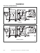
Installation Dimensions and Specifications 5.1 cm (2 in.) 71.1 cm (28 in.) 93.83 cm (36.94 in.) 33.3 cm (13.1 in.) 37.08 cm (14.6 in.) 110.7 cm (43.6 in.) 79 cm (31.1 in.) 75.1 cm (29.6 in.) 61.0 cm (24 in.) 68.3 cm (26.9 in.) 5.1 cm (2 in.) 3.8 cm (1.5 in.) FLW2192N COIN MODELS 71.1 cm (28 in.) 3.8 cm (1.5 in.) 93.8 cm (36.94 in.) 37.1 cm (14.6 in.) 33.3 cm (13.1 in.) 75.1 cm (29.6 in.) 104.6 cm (41.2 in.) 61.0 cm (24 in.) 79 cm (31.1 in.) FLW2192N 68.3 cm (26.9 in.) 5.1 cm (2 in.
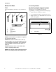
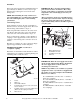
Installation Before You Start Central Pay Models Tools The machine is shipped from the factory with the Electronic Control Diagnostic Harness Assembly unplugged. To avoid unauthorized manual programming or vending perform the following steps. For most installations, the basic tools you will need are: 1. Open service door. Refer to Figure 2. 1 2 3 2. Locate diagnostic harness on electronic control. 4 3. Plug connectors for “white/black” wire and “red/ blue” wire together.
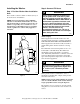
Installation Installing the Washer Step 2: Connect Fill Hoses Step 1: Position Washer Near Installation Area Move washer so that it is within 1.2 meters (4 feet) of the desired area of installation. NOTE: For best performance and to minimize vibration or movement, install washer on a solid, sturdy and level floor. Some floors may need to be reinforced, especially on a second floor or over a basement. Do not install the washer on carpeting, soft tile, a platform or other weakly supported structures.
Installation Turn on the water supply faucets and flush the lines for approximately two minutes to remove any foreign materials that could clog the screens in the water mixing valve. NOTE: When installing in newly constructed or renovated building, it is very important to flush the lines since build-up may have occurred during construction. Connecting Hoses IMPORTANT: Hoses and other natural rubber parts deteriorate after extended use.
Installation Risers Risers (or air cushions) may have to be installed if the pipes knock or pound when flow of water stops. The risers are more efficient when installed as close as possible to the water supply faucets (refer to Figure 6). 1 1 2 FLW1982N W005I W005I 1 2 1 Shipping Tape Risers (Air Cushions) Water Supply Faucets Figure 6 Step 3: Connect Drain Hose to Drain Receptacle Remove the drain hose from its shipping position on the rear of the washer by removing the shipping tape.
Installation Step 4: Position and Level the Washer WARNING Washers elevated above floor level must be anchored to that elevated surface, base or platform. The material used to elevate the washer should also be anchored to the floor to ensure that the washer will not walk or that the washer can not be physically pulled, tipped or slid from its installed position. Failure to do so may result in conditions which can produce serious injury, death and/or property damage.
Installation Step 5: Remove the Shock Sleeves and Shipping Brace Remove front access panel by removing the two screws at the bottom of the panel. Step 6: Wipe Out Inside of Wash Drum Before using washer for the first time, use an all-purpose cleaner, or a detergent and water solution, and a damp cloth to remove shipping dust from inside wash drum. Remove the five bolts and lockwashers from shipping brace with a wrench and remove brace. Refer to Figure 10.
Installation Step 7: Connect the Washer to Electrical Power Electrical Requirements 2 3 1 NOTE: The wiring diagram is located in the control cabinet. 120±12 V.A.C. NOTE: Refer to the washer nameplate on the rear cabinet panel for proper voltage and Hertz the washer is designed to operate on. 0 V.A.C. 120±12 V.A.C. WARNING To reduce the risk of fire, electric shock, serious injury or death, all wiring and grounding MUST conform with the latest edition of the National Electrical Code, ANSI/NFPA No.
Installation 240 Volt, 50 Hertz with 3-Prong Earthing Plug 220 Volt, 60 Hertz without Plug The washer is designed to be operated on a separate branch, polarized, three-wire, effectively earthed, 240 Volt, 50 Hertz, AC (alternating current) circuit protected by a 15 ampere fuse, equivalent fusetron or circuit breaker.
Installation Connecting to Central Pay System 1 IMPORTANT: Any central pay device and related installation wiring that is connected to the washer must maintain the Electromagnetic Compatibility (EMC) of the washer in order to comply with the appropriate national EMC regulatory requirements. The central pay device and related wiring, as a minimum, must meet the emission requirements of EN55014-1 and the immunity requirements of EN55014-2.
Operation Operation Instructions Step 2: Close Loading Door IMPORTANT: Prior to first wash, use an allpurpose cleaner, or a detergent and water solution, and a damp cloth to remove shipping dust from inside of washtub. Close loading door tightly. The washer will not operate with the loading door open. IMPORTANT: Remove all sharp objects from laundry to avoid tears and rips to items during normal machine operation. Step 1: Load Laundry Load items loosely into wash drum (8.1 Kg maximum dry clothes load).
Operation Step 3: Add Laundry Supplies Open dispenser drawer. Measure and add low sudsing, high efficiency (HE) detergent (1), bleach (2) and fabric softener (3) to the dispenser drawer (refer to Figure 17). Close dispenser drawer. IMPORTANT: If using non-HE detergent, avoid oversudsing by using 1/2 of the detergent manufacturer's recommended amount. Step 4: Set Fabric Selector/Wash Temperature Push touchpad for HEAVY, NORMAL, PERM PRESS or DELICATES cycle. Light indicates selection.
Operation Step 6: Start Washer Indicator Lights After vend price has been satisfied, push the START pad. DOOR MUST BE CLOSED TO START WASHER. WASH WASH is lit at the beginning of a wash cycle and will remain lit until the wash cycle is complete. RINSE RINSE is lit at the beginning of all RINSE cycles and will remain lit until the rinse cycle is complete. SPIN SPIN is lit for all spin cycles. DOOR LOCKED DOOR LOCKED is lit whenever the door is locked. The door cannot be opened when this light is on.
Maintenance User-Maintenance Instructions Replacing Hoses Lubrication Hoses and other natural rubber parts deteriorate after extended use. Hoses may develop cracks, blisters or material wear from the temperature and constant high pressure they are subjected to. All moving parts are sealed in a permanent supply of lubricant or are equipped with oilless bearings. Additional lubrication will not be necessary. Do not lubricate the door hinge. If the hinge makes noise, replace the hinge.
Maintenance Reinstallation of Shipping Materials Cleaning Foreign Object Trap To prevent damage while moving the washer, the shipping materials MUST be reinstalled. The washer’s pump has a trap that may collect foreign objects. The trap may need to be cleaned if water is draining slower than usual. To clean: • Disconnect washer from electrical supply. • While supporting the front access panel, remove two screws from the bottom edge of the panel.
Troubleshooting Try these troubleshooting tips before making a service call. They may save you time and money. Washer Symptom Possible Cause/Solution Won’t Fill • • • • • • • • Make sure washer is connected to electrical power. Make sure hot and cold water faucets are turned on. Make sure that the fill hoses are not kinked or twisted. Press START keypad. Make sure that the controls are properly set. Make sure that the loading door is closed tightly. Check the laundry room fuse or circuit breaker.
Troubleshooting Washer Symptom Vibrates/Moves Slightly Possible Cause/Solution • • • Make sure washer is level. Uneven leveling can cause vibration. Make sure washer is installed on a solid, sturdy and level floor. The washer should not be installed on carpeting, soft tile, a platform or other weakly supported structures. Make sure rubber feet are installed on all four leveling legs. Refer to Installation section, step 4. Is Noisy • • Make sure washer is level. Uneven leveling can cause vibration.
Contact Information If service is required, contact the nearest Factory Authorized Service Center. If you are unable to locate an authorized service center or are unsatisfied with the service performed on your unit, contact: When calling or writing about your unit, PLEASE GIVE THE MODEL AND SERIAL NUMBERS. The model and serial numbers are located on the nameplate. The nameplate will be in the location shown in Figure 22.
Installer Checklist Fast Track for Installing the Washer (Refer to the manual for more detailed information) 1 5 • Position Washer Near Installation Area. • Remove the Shock Sleeves and Shipping Brace. FLW2124N FLW2124N CHECK CHECK H054IE0A H054IE0A 2 • Connect Fill Hoses. 6 COLD HOT • Wipe Out Inside of Wash Drum. FLW2135N FLW2135N TLW1976N TLW1976N CHECK CHECK 3 7 • Connect Drain Hose to Drain Receptacle. • Connect the Washer to Electrical Power Source.