INSTRUCTIONS FOR INSTALLATION, USE AND MAINTENANCE CS2000 ASEP2000 (VERSION ASEP2000.
Model Identification Information in this manual is applicable to the following models: UHM027D UHM033D UHM049D UHM067D These technical documents contain information that is privileged and confidential. You are hereby notified that any disclosure or copying is strictly prohibited. We will proceed against any breach of this condition.
TECHNICAL DOCUMENT ASEPTIC AND CS WASHING MACHINE SERIES 2000 CONTENTS 1. General working procedure p. 6 1.1 Description 1.2 Construction 1.2.1 Chassis-frame 1.2.2 Tub and drum 1.2.3 Suspensions 1.2.4 Porthole 1.2.5 Bearings, transmission and motor 1.2.6 Programming 1.3 Working principle 1.4 Security 1.4.1 Total protection against opening doors 1.4.2 Protection against unbalance 1.4.3 Heater protection 1.4.4 Security related to the gas heating system 1.5 Heating 2.
3. Technical information for the user 3.1 Details of the various elements 3.1.1 Opening and closing the doors 3.1.2 Soap trays 3.1.3 Unbalance and direction of rotation 3.2 Usage of washing machines with micro control 4. Periodic maintenance p. 19 p. 19 p. 19 p. 20 p. 20 p. 21 p. 21 4.0 Every day 4.1 Every week 4.2 Every month 4.3 Every 3 months 4.4 Every 6 months 4.5 Every year p. 21 p. 21 p. 21 p. 21 p. 22 p. 22 5. Maintenance instructions p. 23 5.1 Remove sealing kit p. 23 6.
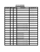
LIST OF DIAGRAMS N° diagram Index Date Description Type machine AS2000-0001 06/01/00 Washer dryer, front view CS, ASEP2000 AS2000-0003 B 19/12/01 Side view CS, ASEP2000 AS2000-0009 A 29/03/00 Tub detail CS, ASEP2000 AS2000-0011 A 25/04/03 Drainage circuit CS ET ASEP2000 AS2000-0015 A 27/06/02 Display DF, CS, ASEP micro AS2000-0016 06/01/00 Electrical heating unit DF, CS, ASEP AS2000-0017 A 03/01/02 Water levels DF, CS, ASEP AS2000-0018 A 25/04/03 Unlocking of tub door, washer DF,
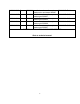
CS2000-0025 D CS2000-0027 B CS2000-0028 B CS2000-0029 C CS2000-0030 B 27/06/02 Installation scheme of aseptic washer elec and steam 2000/67 27/06/02 Installation scheme of aseptic washer gas 2000/27 27/06/02 Installation scheme of aseptic washer gas 2000/33 27/06/02 Installation scheme of aseptic washer gas 2000/49 27/06/02 Installation scheme of aseptic washer gas 2000/67 CS2000/67 E / V CS2000/27 GAS CS2000/33 GAS CS2000/49 GAS CS2000/67 GAS ELECTRICAL DIAGRAMS AND SPARE PARTS LIST Refer to technical m
1. GENERAL WORKING PROCEDURE 1.1 Description • Correct usage in accordance with design: o The dirty laundry is loaded into the front part of the machine and the clean laundry is unloaded from the rear part of the machine, using portholes situated opposite to the loading ports (for the Aseptic machines) or into the front part of the machine (for the CS machines).
1.2 Construction 1.2.1 Chassis - frame • • • Mechanically soldered frame of hot de-scaled steel plating, protected against oxidation by phosphation, and covered with epoxy paint. Protection panels in stainless steel plating with 1.2 mm thickness. The design of the lower part of each tub port inhibits the laundry from slipping inbetween the tub and the drum. 1.2.2 Tub and drum • • The tub consists of a rolled stainless steel plate, closed at its extremities by 2 flanges, also stainless steel.
1.2.6 Programming Of the integral type with a microprocessor, regulation of: • Four soap trays. • Admission of hot, cold and/or soft water. • Bath levels adjustable. • Temperature adjustable from 0 to 90°C with microprocessor. • Reduced mechanical washing motion for delicate laundry. • Normal mechanical washing motion. • Intermediate and final centrifuge. 1.
1.4.2 Protection against unbalance The suspended aseptic or CS machines are fitted with one or two unbalance protections, according to their load capacity. These avoid excessive oscillations caused by a strong unbalance by interrupting the centrifugal motion. Effect of the protections in case of a strong unbalance • During the final centrifuge, the centrifugal motion is interrupted and the drainage is maintained, but the cycle is frozen. The message “E9 or unbalance fault” is shown on the display.
When a fault occurs in the water circulation pump, the power supply of the command module is interrupted and the indicator “pump fault” lights up. When the faults persist, check with qualified technical service. 1.5 Heating Three heating methods are available, providing the flexibility to adapt the machine to the available energy supply. • Electrical heating: by several shielded resistors mounted in the heater bath (the number of resistors being in accordance with the power of the machine).
2. TECHNICAL INFORMATION REGARDING INSTALLATION 2.1 Technical specifications The identification label of machine is situated on upper part of left side of casing.
2.2 Installation Attention: The machine must only be installed, adjusted and started up by a team of technicians of the manufacturer or by technicians or resellers that are recognised by the manufacturer. Likewise, it is strongly recommended that the client be present during the installation and the first trials. The installation of the device must be in accordance with the current regulations and norms and in a room with sufficient ventilation.
2.2.2 Characteristics of the room • • • • The machine must be installed in a very well ventilated room with correct lighting and a temperature in the range from -10 to + 40°C (temperature limits for the electronic frequency regulator of the driving motor) . Sufficient space must be left around the machine to allow for its correct functioning. On each side sufficient space must be left in front of the portholes so that the machine operator can work correctly and without danger.
2.2.3 Connections Water supply connection: All machines are fitted with two water supply connections (hot and cold water). Please consult manufacturer for optional soft water connection. For machines with gas heating, it is important to ensure correct operation of boiler, to supply water for washing step with a maximum TH of 10°. A higher TH will involve a permanent clogging of boiler. Install two pipes (hot and cold water) vertically behind machine; install two blocking valves in an accessible location.
Wire colors THREE 380 V + N + T Black - black - brown ...….... Phases Blue ..................................... Neutral Green / yellow ..................... Earth THREE 220 V + T Black - brown - blue ........... Phases Green / yellow..................... Earth Important: Install an additional upstream fuse cabinet. Furthermore, install a residual current operated circuit breaker (300 ma) for the general protection of your launderette against electrical faults.
Steam connection: • • The steam pressure must be between 5 and 10 bars. Install a steam escape valve to avoid overpressure.
Connection with exhaust conduct Place draught-diverter system supplied with the device between the exit of the heater and the gas exhaust conduct. The tubes that connect with the chimney are of diameter 150 and should be as short as possible. 2.2.4 First start-up • • • • • • • Verify that the machine is stable and level upon first start-up. Check that all connections and drains are correctly established. Check that the device is connected to earth correctly.
2.3.2 Table of adjustments and flow rates Gas type G20 Pres. feed.(mbar) 20 Injector marking 180 Adjustment of air pres. Max opening of Idem vent Flow of burner 2.64(cubic m/h) 3.07(cubic m/h) 1.96 (kg / h) 1.96 (kg / h) Nominal heat flow kW (hi) 24.9 24.9 (1) G31 G31 20 37 50 200 120 110 Idem Idem G25 (2) 24.9 24.
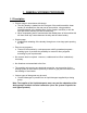
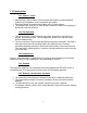
3. TECHNICAL INFORMATION FOR THE USER Note: • The user must not handle parts that are protected by the manufacturer or his representative. • The user must appeal to a qualified installer to adapt the device to a different type of gas. • The exhaust gas evacuation chimney must be swept periodically in accordance with the valid rules of the concerned country. 3.1 Details of the various elements 3.1.
3.1.2 Soap trays Attention: All products used are harmful and must be handled with caution. Read the recommendations of the product suppliers carefully. Before all manipulation: you must use appropriate protective clothing, e.g. gloves, boots, glasses, respiratory masks, etc. Detergent: • Fill the soap trays with the corresponding products when starting a cycle. • The detergents for washing and pre-washing must be in powder form (or liquid when automatic feeding by a dosing pump is used).
Note: Centrifuge must always switch on with the same velocity and direction as the washing rotation. This rotation is downward when you are on the dirty laundry side of the machine. 3.2 Usage of washing machines with micro control Refer to Programming Manual for micro control information. 4. PERIODIC MAINTENANCE 4.0 Every day Clean dust filter located below the tub once a day when using gas heating. 4.1 Every week (0.5 h) • • Clean the soap trays.
• • De-scale the heater unit using a de-scaling product (consult manufacturer for supplies) on those machines that use gas heating. This product is introduced in the tub of the washing machines. Then, a washing cycle at 60°C is carried out lasting about 20 minutes, after which the machine is drained and rinsed. Check the working condition of the door locking system of the drum ports: o The spring of both latches. o The spring of the holding receptacle of the controller rod. 4.
5. MAINTENANCE INSTRUCTIONS 5.1 Replacement of the sealing kit 1) Remove the strips. 2) Remove the hub (remove the two hub screws and place one of the two screws in the third hole). 3) Remove the wheel (first make a mark so you can later replace it in the same position). 4) Secure the drum with two wooden wedges. 5) Remove the cover and clean off the lubricant. 6) Release the flap of the blocking washer that is fixed by a screw. 7) Undo the screw until the base of the conical section.
6. TROUBLESHOOTING 6.1 Checks • • • • • • • • The electrical power supply. The protective fuses. Water supply interruption. Filter blocking. Water pressure failure. Waterproofing of the drainage system. The driving belts. The water levels. Attention: When the water levels are not correct, consult reseller and replace the pressure switch. • • • When the drainage is obstructed, clean it. When the machine vibrates, check the following: o It is loaded with a heterogeneous load of laundry.
7.
-------------------------------------------------------------------------------------------Machine does not drain - drainage valve dirty - exhaust tube blocked -------------------------------------------------------------------------------------------Machine does not centrifugate - improper loading of laundry or loading limits not respected, causing an unbalance fault - no high level before centrifugation - drainage blocked ------------------------------------------------------------------------------------
PROGRAM DETAILS ASEPTIC WASHING MACHINE TYPE 2000/CS 2000 WITH MICRO CONTROL PROGRAM N°: STAGE LAUNDRY TYPE: VERY SOILED WHITE Wash energic speed: 45 tr/min 1 TIME LEVEL WATER TYPE Soaking PRODUCT TEMP.
PROGRAM DETAILS ASEPTIC WASHING MACHINE TYPE 2000/CS 2000 WITH MICRO CONTROL PROGRAM N°: STAGE LAUNDRY TYPE: SOILED WHITE Wash energic speed: 45 tr/min 2 TIME LEVEL WATER TYPE Soaking PRODUCT TEMP.
PROGRAM DETAILS ASEPTIC WASHING MACHINE TYPE 2000/CS 2000 WITH MICRO CONTROL PROGRAM N°: LAUNDRY TYPE: COLOUR Wash energic speed: 45 tr/min 3 STAGE TIME Soaking LEVEL WATER TYPE PRODUCT TEMP.
PROGRAM DETAILS ASEPTIC WASHING MACHINE TYPE 2000/CS 2000 WITH MICRO CONTROL PROGRAM N°: LAUNDRY TYPE: POLYESTER/ COTON Wash energic speed: 45 tr/min 4 STAGE TIME WATER TYPE LEVEL PRODUCT TEMP.
PROGRAM DETAILS ASEPTIC WASHING MACHINE TYPE 2000/CS 2000 WITH MICRO CONTROL PROGRAM N°: LAUNDRY TYPE: WOOLEN Wash energic speed: 45 tr/min 5 STAGE TIME Soaking WATER TYPE LEVEL PRODUCT TEMP.
PROGRAM DETAILS ASEPTIC WASHING MACHINE TYPE 2000/CS 2000 WITH MICRO CONTROL LAUNDRY TYPE: Wash energic speed: PROGRAM N°: STAGE TIME Soaking WATER TYPE LEVEL PRODUCT Prewash Wash 1 Wash 2 Cooling Rinsing 1 Bleaching Rinsing 2 Rinsing 3 Rinsing 4 Rinsing final Centrifugation : Distribution 1 Distribution 2 Centrifugation 1 Centrifugation 2 Centrifugation 3 Separation Additional information: Duration of product drainages: Tray A: Tray B: Tray C: Tray D: 50 50 50 50 Rinsing tray: 60 Note: -
Cycle n.1 1. 2. 3. 4. 5. 6. 7. 8. Step n. 2 Step n. 3 Step n. 4 Step n. 5 Step n. 4 Step n. 6 Step n. 7 Step n. 8 Prewash Wash Rinse Rinse Rinse Rinse Spin Distribution PREWASH38 WASH80 RINSE120 BLEACH240 RINSE120 FINALRINS SPIN1000 TUMBLE60 Cycle n.2 1. 2. 3. 4. 5. 6. Step n. 9 Step n. 5 Step n. 4 Step n. 6 Step n. 7 Step n. 8 Wash Rinse Rinse Rinse Spin Distribution WASH80 BLEACH240 RINSE120 FINALRINS SPIN1000 TUMBLE60 1. 2. 3. 4. 5. 6. 7. Step n. 10 Step n. 11 Step n. 4 Step n. 4 Step n.
Step n. 1 Soak ENABLE SPEED VLL VLN VDN VDA VCL VCI VCA NO YES NO NO NO NO NO DRUM ACTION Move Pause 15 sec. 10 sec. SET TEMPERATURE HEATING Temperature Maintain time COOLING Temperature 2° Level 0 °C 4 cm. WATER LEVEL TO BE REACHED Water level Maintain time Alarm timeout 27 cm. 120 sec. 0 sec. FILLING WATER INTAKE ACVAS = WARM WATER ADUV = HARD WATER ADOVAS = SOFT WATER Drum movement NO YES NO YES DRAIN Drain enabling delay Drum movement End step unload 0 sec. YES YES SOAP INTAKE ADOL(disp.
Step n. 2 Prewash ENABLE SPEED VLL VLN VDN VDA VCL VCI VCA NO YES NO NO NO NO NO DRUM ACTION Move Pause 15 sec. 10 sec. SET TEMPERATURE HEATING Temperature Maintain time COOLING Temperature 2° Level 0 °C 4 cm. WATER LEVEL TO BE REACHED Water level Maintain time Alarm timeout 27 cm. 240 sec. 0 sec. FILLING WATER INTAKE ACVAS = WARM WATER ADUV = HARD WATER ADOVAS = SOFT WATER Drum movement NO YES NO YES DRAIN Drain enabling delay Drum movement End step unload 0 sec.
Step n. 3 Wash ENABLE SPEED VLL VLN VDN VDA VCL VCI VCA NO YES NO NO NO NO NO DRUM ACTION Move Pause 15 sec. 10 sec. SET TEMPERATURE HEATING Temperature Maintain time COOLING Temperature 2° Level 0 °C 4 cm. WATER LEVEL TO BE REACHED Water level Maintain time Alarm timeout 21 cm. 300 sec. 0 sec. FILLING WATER INTAKE ACVAS = WARM WATER ADUV = HARD WATER ADOVAS = SOFT WATER Drum movement YES NO NO YES DRAIN Drain enabling delay Drum movement End step unload 0 sec. YES YES SOAP INTAKE ADOL(disp.
Step n. 4 Rinse ENABLE SPEED VLL VLN VDN VDA VCL VCI VCA NO YES NO NO NO NO NO DRUM ACTION Move Pause 15 sec. 10 sec. SET TEMPERATURE HEATING Temperature Maintain time COOLING Temperature 2° Level 0 °C 4 cm. WATER LEVEL TO BE REACHED Water level Maintain time Alarm timeout 27 cm. 120 sec. 0 sec. FILLING WATER INTAKE ACVAS = WARM WATER ADUV = HARD WATER ADOVAS = SOFT WATER Drum movement NO YES NO YES DRAIN Drain enabling delay Drum movement End step unload 0 sec. YES YES SOAP INTAKE ADOL(disp.
Step n. 5 Rinse BLEACH240 ENABLE SPEED VLL VLN VDN VDA VCL VCI VCA NO YES NO NO NO NO NO DRUM ACTION Move Pause 15 sec. 10 sec. SET TEMPERATURE HEATING Temperature Maintain time COOLING Temperature 2° Level 0 °C 4 cm. WATER LEVEL TO BE REACHED Water level Maintain time Alarm timeout 24 cm. 240 sec. 0 sec. FILLING WATER INTAKE ACVAS = WARM WATER ADUV = HARD WATER ADOVAS = SOFT WATER Drum movement NO YES NO YES DRAIN Drain enabling delay Drum movement End step unload 0 sec.
Step n. 6 Rinse ENABLE SPEED VLL VLN VDN VDA VCL VCI VCA NO YES NO NO NO NO NO DRUM ACTION Move Pause 15 sec. 10 sec. SET TEMPERATURE HEATING Temperature Maintain time COOLING Temperature 2° Level 0 °C 4 cm. WATER LEVEL TO BE REACHED Water level Maintain time Alarm timeout 27 cm. 240 sec. 0 sec. FILLING WATER INTAKE ACVAS = WARM WATER ADUV = HARD WATER ADOVAS = SOFT WATER Drum movement YES YES NO YES DRAIN Drain enabling delay Drum movement End step unload 0 sec. YES NO SOAP INTAKE ADOL(disp.
Step n. 7 Spin ENABLE SPEED VLL VLN VDN VDA VCL VCI VCA START WITH WATER 0 sec. 0 sec. 5 sec. 60 sec. 120 sec. 240 sec. 120 sec. YES TILTING Number of spin attempts 6 Step n. 8 Distribution ENABLE SPEED VLL VLN VDN VDA VCL VCI VCA 0 sec. 60 sec. 0 sec. 0 sec. 0 sec. 0 sec. 0 sec. DRUM ACTION Move Pause 10 sec. 5 sec.
Step n. 9 Wash ENABLE SPEED VLL VLN VDN VDA VCL VCI VCA NO YES NO NO NO NO NO DRUM ACTION Move Pause 15 sec. 10 sec. SET TEMPERATURE HEATING Temperature Maintain time COOLING Temperature 2° Level 0 °C 4 cm. WATER LEVEL TO BE REACHED Water level Maintain time Alarm timeout 21 cm. 480 sec. 0 sec. FILLING WATER INTAKE ACVAS = WARM WATER ADUV = HARD WATER ADOVAS = SOFT WATER Drum movement YES NO NO YES DRAIN Drain enabling delay Drum movement End step unload 0 sec. YES YES SOAP INTAKE ADOL(disp.
Step n. 10 Prewash ENABLE SPEED VLL VLN VDN VDA VCL VCI VCA NO YES NO NO NO NO NO DRUM ACTION Move Pause 15 sec. 10 sec. SET TEMPERATURE HEATING Temperature Maintain time COOLING Temperature 2° Level 0 °C 4 cm. WATER LEVEL TO BE REACHED Water level Maintain time Alarm timeout 27 cm. 180 sec. 0 sec. FILLING WATER INTAKE ACVAS = WARM WATER ADUV = HARD WATER ADOVAS = SOFT WATER Drum movement NO YES NO YES DRAIN Drain enabling delay Drum movement End step unload 0 sec.
Step n. 11 Wash ENABLE SPEED VLL VLN VDN VDA VCL VCI VCA NO YES NO NO NO NO NO DRUM ACTION Move Pause 15 sec. 10 sec. SET TEMPERATURE HEATING Temperature Maintain time COOLING Temperature 2° Level 0 °C 4 cm. WATER LEVEL TO BE REACHED Water level Maintain time Alarm timeout 21 cm. 300 sec. 0 sec. FILLING WATER INTAKE ACVAS = WARM WATER ADUV = HARD WATER ADOVAS = SOFT WATER Drum movement YES YES NO YES DRAIN Drain enabling delay Drum movement End step unload 0 sec. YES YES SOAP INTAKE ADOL(disp.
Step n. 12 Spin ENABLE SPEED VLL VLN VDN VDA VCL VCI VCA START WITH WATER 0 sec. 0 sec. 5 sec. 60 sec. 120 sec. 300 sec. 120 sec.
Step n. 14 Wash ENABLE SPEED VLL VLN VDN VDA VCL VCI VCA NO YES NO NO NO NO NO DRUM ACTION Move Pause 15 sec. 10 sec. SET TEMPERATURE HEATING Temperature Maintain time COOLING Temperature 2° Level 45 °C 7 cm. WATER LEVEL TO BE REACHED Water level Maintain time Alarm timeout 21 cm. 480 sec. 0 sec. FILLING WATER INTAKE ACVAS = WARM WATER ADUV = HARD WATER ADOVAS = SOFT WATER Drum movement NO YES NO YES DRAIN Drain enabling delay Drum movement End step unload 0 sec. YES YES SOAP INTAKE ADOL(disp.
Step n. 15 Rinse ENABLE SPEED VLL VLN VDN VDA VCL VCI VCA NO YES NO NO NO NO NO DRUM ACTION Move Pause 15 sec. 10 sec. SET TEMPERATURE HEATING Temperature Maintain time COOLING Temperature 2° Level 0 °C 4 cm. WATER LEVEL TO BE REACHED Water level Maintain time Alarm timeout 27 cm. 180 sec. 0 sec. FILLING WATER INTAKE ACVAS = WARM WATER ADUV = HARD WATER ADOVAS = SOFT WATER Drum movement NO YES NO YES DRAIN Drain enabling delay Drum movement End step unload 0 sec. YES YES SOAP INTAKE ADOL(disp.
Step n. 16 Rinse ENABLE SPEED VLL VLN VDN VDA VCL VCI VCA NO YES NO NO NO NO NO DRUM ACTION Move Pause 15 sec. 10 sec. SET TEMPERATURE HEATING Temperature Maintain time COOLING Temperature 2° Level 0 °C 4 cm. WATER LEVEL TO BE REACHED Water level Maintain time Alarm timeout 27 cm. 240 sec. 0 sec. FILLING WATER INTAKE ACVAS = WARM WATER ADUV = HARD WATER ADOVAS = SOFT WATER Drum movement NO YES NO YES DRAIN Drain enabling delay Drum movement End step unload 0 sec. YES NO SOAP INTAKE ADOL(disp.
Step n. 17 Spin ENABLE SPEED VLL VLN VDN VDA VCL VCI VCA START WITH WATER 0 sec. 0 sec. 5 sec. 60 sec. 120 sec. 300 sec. 0 sec.
Step n. 18 Wash ENABLE SPEED VLL VLN VDN VDA VCL VCI VCA NO YES NO NO NO NO NO DRUM ACTION Move Pause 15 sec. 10 sec. SET TEMPERATURE HEATING Temperature Maintain time COOLING Temperature 2° Level 0 °C 4 cm. WATER LEVEL TO BE REACHED Water level Maintain time Alarm timeout 21 cm. 300 sec. 0 sec. FILLING WATER INTAKE ACVAS = WARM WATER ADUV = HARD WATER ADOVAS = SOFT WATER Drum movement YES YES NO YES DRAIN Drain enabling delay Drum movement End step unload 0 sec. YES YES SOAP INTAKE ADOL(disp.
Step n. 19 Wash ENABLE SPEED VLL VLN VDN VDA VCL VCI VCA NO YES NO NO NO NO NO DRUM ACTION Move Pause 4 sec. 10 sec. SET TEMPERATURE HEATING Temperature Maintain time COOLING Temperature 2° Level 0 °C 4 cm. WATER LEVEL TO BE REACHED Water level Maintain time Alarm timeout 21 cm. 480 sec. 0 sec. FILLING WATER INTAKE ACVAS = WARM WATER ADUV = HARD WATER ADOVAS = SOFT WATER Drum movement NO YES NO YES DRAIN Drain enabling delay Drum movement End step unload 0 sec. YES YES SOAP INTAKE ADOL(disp.
Step n. 20 Rinse ENABLE SPEED VLL VLN VDN VDA VCL VCI VCA NO YES NO NO NO NO NO DRUM ACTION Move Pause 4 sec. 10 sec. SET TEMPERATURE HEATING Temperature Maintain time COOLING Temperature 2° Level 0 °C 4 cm. WATER LEVEL TO BE REACHED Water level Maintain time Alarm timeout 27 cm. 180 sec. 0 sec. FILLING WATER INTAKE ACVAS = WARM WATER ADUV = HARD WATER ADOVAS = SOFT WATER Drum movement NO YES NO YES DRAIN Drain enabling delay Drum movement End step unload 0 sec. YES YES SOAP INTAKE ADOL(disp.
Step n. 21 Rinse ENABLE SPEED VLL VLN VDN VDA VCL VCI VCA NO YES NO NO NO NO NO DRUM ACTION Move Pause 4 sec. 10 sec. SET TEMPERATURE HEATING Temperature Maintain time COOLING Temperature 2° Level 0 °C 4 cm. WATER LEVEL TO BE REACHED Water level Maintain time Alarm timeout 27 cm. 240 sec. 0 sec. FILLING WATER INTAKE ACVAS = WARM WATER ADUV = HARD WATER ADOVAS = SOFT WATER Drum movement NO YES NO YES DRAIN Drain enabling delay Drum movement End step unload 0 sec. YES NO SOAP INTAKE ADOL(disp.
Step n. 22 Spin ENABLE SPEED VLL VLN VDN VDA VCL VCI VCA START WITH WATER 0 sec. 0 sec. 5 sec. 60 sec. 120 sec. 0 sec. 0 sec.