Installation Washer-Extractors Cabinet Hardmount Refer to Page 6 for Model Identification CHM1772C CHM1772C Keep These Instructions for Future Reference. (If this machine changes ownership, this manual must accompany machine.) www.comlaundry.com Part No.
Table of Contents Safety Information.............................................................................. Explanation of Safety Messages........................................................... Important Safety Instructions ............................................................... Safety Decals ........................................................................................ Operator Safety.....................................................................................
Safety Information Explanation of Safety Messages Precautionary statements (“DANGER,” “WARNING,” and “CAUTION”), followed by specific instructions, are found in this manual and on machine decals. These precautions are intended for the personal safety of the operator, user, servicer, and those maintaining the machine. DANGER DANGER indicates the presence of a hazard that will cause severe personal injury, death, or substantial property damage if the danger is ignored.
Safety Information 11. Do not repair or replace any part of the washer, or attempt any servicing unless specifically recommended in the user-maintenance instructions or in published user-repair instructions that the user understands and has the skills to carry out. 23. Always read and follow manufacturer’s instructions on packages of laundry and cleaning aids. Heed all warnings or precautions.
Safety Information WARNING CAUTION This machine must be installed, adjusted, and serviced by qualified electrical maintenance personnel familiar with the construction and operation of this type of machinery. They must also be familiar with the potential hazards involved. Failure to observe this warning may result in personal injury and/or equipment damage, and may void the warranty. SW004 IMPORTANT: Ensure that the recommended clearances for inspection and maintenance are provided.
Safety Information Operator Safety Do not bypass any safety devices in the machine. WARNING WARNING NEVER insert hands or objects into basket until it has completely stopped. Doing so could result in serious injury. SW012 Operating the machine with severe out-ofbalance loads could result in personal injury and serious equipment damage. W728 To ensure the safety of machine operators, the following maintenance checks must be performed daily: 1.
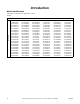
Introduction Model Identification Information in this manual is applicable to these models: 20 POUND Model HCD020GD2 HCD020JD2 HCD020LD2 HCL020GD2 HCL020GN2 HCL020HDF HCL020HN2 HCL020KD2 HCL020LD2 HCN020GC2 HCN020GD2 HCN020GE2 HCN020GN2 HCN020GX2 HCN020GY2 HCN020HC2 HCN020HCF HCN020HD2 HCN020HN2 HCN020HNF HCN020HY2 HCN020HYF HCN020KC2 HCN020KCF HCN020KCV HCN020KD2 HCN020KDV HCN020KEF HCN020KEV HCN020KY2 HCN020KYF HCN020KYV HCU020GC2 HCU020GD2 HCU020GE2 HCU020GL2 HCU020GN2 HCU020GX2 HCU020GY2 HCU020HC2 HC
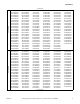
Introduction 30 POUND HCD030LD2 HCL030GN2 HCL030HDF HCL030HN2 HCL030HNF HCN030GC2 HCN030GD2 HCN030GE2 HCN030GN2 HCN030GX2 HCN030GY2 HCN030HC2 HCN030HCF HCN030HD2 HCN030HN2 HCN030HNF HCN030HY2 HCN030HYF HCN030KC2 HCN030KCF HCN030KCV HCN030KD2 HCN030KDV HCN030KEF HCN030KY2 HCN030KYF HCN030KYV HCU030GC2 HCU030GD2 HCU030GE2 HCU030GL2 HCU030GN2 HCU030GX2 HCU030GY2 HCU030HC2 HCU030HN2 HCU030HNF HCU030HX2 HCU030KCF HCU030KCV HCU030KE2 HCU030KY2 HCU030KYF HCU030KYV HCZ030GN2 SCD030GD2 SCD030LD2 SCL030GC2 SCL030G
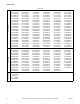
Introduction 8 60 POUND HCD060LD2 HCL060GN2 HCL060HCF HCL060HN2 HCN060GC2 HCN060GD2 HCN060GE2 HCN060GN2 HCN060GX2 HCN060GY2 HCN060HC2 HCN060HCF HCN060HN2 HCN060HNF HCN060HY2 HCN060HYF HCN060KC2 HCN060KCF HCN060KCV HCN060KD2 HCN060KDF HCN060KDV HCN060KEV HCN060KEF HCN060KY2 HCN060KYF HCN060KYV HCU060GC2 HCU060GD2 HCU060GE2 HCU060GL2 HCU060GN2 HCU060GX2 HCU060GY2 HCU060HC2 HCU060HN2 HCU060HNF HCU060HX2 HCU060KCF HCU060KCV HCU060KEV HCU060KY2 HCU060KYF HCU060KYV SCD060GD2 SCD060LD2 SCL060GC2 SCL060GN2 SCL
Introduction This manual is designed as a guide to the installation of the Cabinet Hardmount Washer-Extractor. NOTE: All information, illustrations, and specifications contained in this manual are based on the latest product information available at the time of printing. We reserve the right to make changes at any time without notice. Nameplate Location The nameplate is located at the rear of the machine and inside door.
Introduction Model Number Familiarization Guide Sample Model Number: *CN040GC2OU1D01 *C Product Family N Agency Approval 040 Washer-Extractor Capacity (pounds dry weight of laundry) G Type of Electrical Control C Actuation (C = Coin drop) 2 Washer-Extractor Speed Capability (2 = 2 speed) O Electrical Characteristics U Panel Type 1 Design Series D Heat Feature (D = Direct Steam) 01 Option Identification (varies from machine to machine) * Denotes Brand *CN040GC2OUID01 00000000000 Mode
Introduction Replacement Parts If literature or replacement parts are required, contact the source from which the machine was purchased or contact Alliance Laundry Systems at (920) 748-3950 for the name and address of the nearest authorized parts distributor. Customer Service For technical assistance, contact your local distributor or call: Alliance Laundry Systems (920) 748-3121 Ripon, Wisconsin U.S.A.
Specifications and Dimensions 2 Speed Models Specification 20 30 40 60 Net weight, lbs. (kg) 387 (176) 489 (222) 692 (314) 812 (368) Domestic shipping weight, lbs. (kg) 420 (191) 530 (240) 734 (333) 854 (387) Domestic shipping volume, ft.3 (m3) 30.5 (.86) 40.75 (1.15) 50 (1.42) 64 (1.81) Export shipping weight, lbs. (kg) 475 (215) 593 (269) 816 (370) 948 (430) Export shipping volume, ft.3 (m3) 36.2 (1.03) 49.9 (1.41) 60 (1.70) 75.8 (2.15) Cylinder diameter, in.
Specifications and Dimensions 2 Speed Models (Continued) Specification 20 30 40 60 Door opening diameter, in. (mm) 11.63 (295) 14.34 (364) 16.25 (413) 16.25 (413) Height of door bottom above floor, in. (mm) 14.38 (365) 14 (356) 14.5 (368) 15 (381) Height of door opening above floor, in. (mm) 17.19 (437) 17 (431) 19 (483) 18.5 (470) 400 (101) 450 (113) 510 (129) 750 (189) No load .06 .13 .196 .25 Sheets .10 .14 .195 .26 Towels .11 .16 .213 .
Specifications and Dimensions 2 Speed Models (Continued) Specification 20 30 40 60 Steam inlet connection size, NPT N/A N/A 1/2 1/2 Number of steam inlets N/A N/A 1 1 LOW N/A N/A 2.09 (0.84) 3.6 (0.895) MED N/A N/A 2.40 (1.15) 4.4 (1.384) HIGH N/A N/A 2.84 (1.48) 5.5 (1.916) N/A 0.73 (6.9) 1.43 (12.2) 2.32 (15.4) 200V 5.4 5.4 10.8 10.8 240V 7.8 7.8 15.6 15.6 380V 6.5 6.5 13.0 13.0 415V 7.8 7.8 15.5 15.5 480V 10.4 10.4 15.6 15.6 3 3 6 6 2.6 2.
Specifications and Dimensions V-Speed and F-Speed Models Specification 20 30 40 60 80 125 Net weight, lbs. (kg) 386 (175) 498 (226) 706 (321) 773 (350) 1374 (623) 2301 (1044) Domestic shipping weight, lbs. (kg) 424 (191) 545 (245) 744 (338) 824 (373) 1461 (663) 2384 (1081) Domestic shipping volume, ft.3 (m3) 27 (0.76) 34.4 (.98) 43.6 (1.24) 52.2 (1.48) 102.2 (2.89) 163 (4.3) Export shipping weight, lbs.
Specifications and Dimensions V-Speed and F-Speed Models (Continued) Specification 20 30 40 60 80 125 Gentle wash/reverse speed, RPM 29 27 26 26 22 26 Wash/reverse speed, RPM 52 52 46 43 40 37 Distribution speed, RPM 92 92 82 77 70 65 Low extract speed, RPM 366 366 328 307 280 260 Medium extract speed, RPM (Not available on Electronic Control models) 534 534 478 447 408 378 High extract speed, RPM 686 686 613 574 524 485 Gentle wash centrifugal force, G 0.
Specifications and Dimensions NOTE: The dimensions shown are for planning purposes only. They are approximate and subject to normal manufacturing tolerances. If exact dimensions are required for construction purposes, contact the distributor or manufacturer. We reserve the right to make changes at any time without notice.
Specifications and Dimensions Machine Capacity Dimensions Dimensions 20 30 40 60 80 A 35.15 in. (893 m) 38.03 in. (966 mm) 40.31 in. (1024 mm) 43.31 in. (1100 mm) 51.87 in. (1317 mm) B 34.52 in. (877 mm) 37.46 in. (951 mm) 39.71 in. (1009 mm) 42.4 in. (1077 mm) 48.68 in. (1236 mm) C 1.81 in. (46 mm) 1.73 in. (44 mm) 2.97 in. (75 mm) 2.42 in. (61 mm) 2.71 in. (69 mm) D 4.5 in. (114 mm) 4.5 in. (114 mm) 4.81 in. (122 mm) 4.69 in. (119 mm) 5.71 in. (145 mm) Standard 5.88 in.
Specifications and Dimensions F 2 D 4 E 5 6 7 8 P 1 3 A G Q H L M B C I 9 N O J K 125 POUND CAPACITY MACHINES CHM2279N CHM2279N 1 2 3 4 5 Dry Chemical Dispenser (Optional) Input Power Block Compartment Fans Valve Panel Cold Water Inlet 6 7 8 9 Hot Water Inlet Liquid Chemical Inlet Steam Inlet (Optional) Drain Outlet Figure 4 Machine Capacity Dimensions for 125 Pound Models through 1/31/11 A 78.8 in. (2002 mm) J 61.28 in. (1557 mm) B 14.62 in. (371 mm) K 70.81 in.
Specifications and Dimensions F 2 D 4 E 5 6 7 8 P 1 3 A G Q H L M B C I 9 N O J K CHM2345N 125 POUND CAPACITY MACHINES CHM2345N 1 Dry Chemical Dispenser (Optional on OPL Models) Input Power Block Compartment Fans Valve Panel 2 3 4 5 6 7 8 9 Cold Water Inlet Hot Water Inlet Liquid Chemical Inlet Steam Inlet (Optional) Drain Outlet Figure 5 Machine Capacity Dimensions for 125 Pound Models starting 2/1/11 20 A 63.04 in. (1601 mm) J 49.02 in. (1245 mm) B 11.69 in.
Specifications and Dimensions Dimensional Clearances C FRONT A B CHM2280N CHM2280N Dimensions A B Recommended C Minimum F8208301 Machine Capacity Dimensional Clearances 20 30 40 60 2 in. 2 in. 2 in. 2 in. (51 mm) (51 mm) (51 mm) (51 mm) .5 in. .5 in. .5 in. .5 in. (12.5 mm) (12.5 mm) (12.5 mm) (12.5 mm) 24 in. 24 in. 24 in. 24 in. (610 mm) (610 mm) (610 mm) (610 mm) 12 in. 12 in. 12 in. 12 in. (305 mm) (305 mm) (305 mm) (305 mm) 80 6 in. (152 mm) .5 in. (12.5 mm) 24 in. (610 mm) 18 in.
Installation Machine Foundation NOTE: Do not mount on wooden floors, tile floors, above ground level, or over basements or crawl spaces because of the high extract speed and the G-forces exerted. Thoroughness of detail must be stressed with all foundation work to ensure a stable unit installation, eliminating possibilities of excessive vibration during the extract cycle. The floor and foundation must be minimum 4000 psi reinforced concrete set firmly in clean, compacted fill dirt.
Installation Refer to Table 2 and Table 3 for static and dynamic loads on the floor or foundation. Floor Load Data, 2 Speed Models Specification 20 30 40 60 Static floor load, lbs. (kN) 449 (1.99) 622 (2.76) 903 (4.0) 1099 (4.9) Static pressure, lbs.-ft.2 (kN-m2) 97.8 (4.68) 101 (4.84) 118 (5.65) 120 (5.75) Dynamic load, lbs. (kN) 374 (1.66) 495 (2.2) 898 (3.99) 1404 (6.3) Dynamic pressure, lbs.-ft.2 (kN-m2) 165.3 (7.91) 169 (8.09) 216 (10.3) 253 (12.
Installation Concrete Foundation Installation A concrete foundation pad may be constructed to elevate the machines. The concrete foundation pad must be poured, reinforced with rebar and tied to the existing floor with reinforcing bars. Refer to Figure 6, Figure 7 or Figure 8 for a typical concrete foundation pad installation. WARNING 1. Verify that the floor meets the requirements given in the Machine Foundation section. 2.
Installation 4. Use rebar or other appropriate material to ensure that the concrete foundation will be sufficiently connected to the existing floor. 5. If desired, prepare a form for the above-ground portion of the foundation and fill form and excavation with concrete to join the foundation. Verify that top of foundation is level. The height of the foundation must not exceed 8 inches (203 mm). 6. Use the mounting bolt layout to properly position the mounting bolts in the wet concrete.
Installation A B B LENGTH FOR ONE MACHINE B C D COMPACTED FILL DIRT 18 in. (457 mm) DEPTH COMPACTED FILL DIRT 18 in. (457 mm) DEPTH CHM2282N 80 MODELS CHM2282N A B 9 in. (229 mm) 6 in. (152 mm) C D 47.5 in. (1207 mm) 4 ft. 6 in. (1372 mm) Figure 7 A B A C LENGTH FOR ONE MACHINE A D COMPACTED FILL DIRT 24 in. (609 mm) DEPTH COMPACTED FILL DIRT 24 in. (609 mm) DEPTH CHM2283N 125 MODELS CHM2283N A B 12 in. (305 mm) 6 in. (152 mm) C D 48 in. (1219 mm) 6 ft.
Installation Machine Anchoring Before anchoring the machine, refer to Table 1 to determine the appropriate method of anchoring for the machine. NOTE: Improper installation may void the warranty. Consult the manufacturer or distributor before varying from a procedure. Direct-to-Finished-Floor Installation Installing With Expansion Bolts for 2 Speed Models NOTE: Expansion bolts are not suitable for variable-speed machine installations. 1.
Installation The completed expansion bolt installation is shown in Figure 10. NOTE: Check and retighten the nuts after five to ten days of operation and every three months thereafter. 3 2 4 1 5 1.5 in. (38.
Installation 3. Refer to Figure 9 and Table 4 to set the drill depth gauge. 4. Drill the holes to the set depth. Refer to Table 4. 5. Use compressed air or a squeeze bulb to remove debris from each hole. 6. Fill half the hole depth with an industry accepted adhesive anchoring system. 7. Insert bolt until it reaches the bottom of the hole and 1.5 inches (38 mm) of the bolt extends above the base frame. Refer to Figure 10. 8. Allow adhesive around the bolt to cure properly. 9.
Installation Mounting Bolt Hole Locations (Without Elevated Base Frames) 26 in. (660 mm) 2.67 in. (68 mm) 2.67 in. (68 mm) 25-44 in. (646 mm) 23.94 in. (608 mm) 20.66 in. (525 mm) 14.31 in. (363 mm) 31.75 in. (806 mm) 0.75 in. (19 mm) 25.22 in. (641 mm) 20.88 in. (530 mm) 2.56 in. (65 mm) 20 Models Front of Front Panel 2.56 in. (65 mm) CHM2224N Figure 13 IMPORTANT: Drawing is not to scale.
Installation Mounting Bolt Hole Locations (Without Elevated Base Frames) 29 in. (737 mm) 2.75 in. (70 mm) 23.5 in. (597 mm) 28.94 in. (735 mm) 2.75 in. (70 mm) 30.5 in. (775 mm) 18.44 in. (468 mm) 37.52 in. (953 mm) 30.02 in. (762 mm) 0.75 in. (19 mm) Front of Frame 23.88 in. (607 mm) 30 Models 2.56 in. (65 mm) Front of Front Panel 2.56 in. (65 mm) CHM2063N Figure 14 IMPORTANT: Drawing is not to scale.
Installation 32.5 in. (826 mm) Mounting Bolt Hole Locations (Without Elevated Base Frames) 23.63 in. (600 mm) 3.5 in. (89 mm) 20 in. (508 mm) 36 in. (914 mm) 41.63 in. (1057 mm) 31.88 in. (810 mm) Front of Frame 0.75 in. (19 mm) 0.75 in. (19 mm) 1.75 in. (45 mm) 26 in. (660 mm) Front of Front Panel 30.63 in. (778 mm) 40 Models 2.32 in. (59 mm) CHM206 CHM2067N Figure 15 IMPORTANT: Drawing is not to scale.
Installation Mounting Bolt Hole Locations (Without Elevated Base Frames) 34.06 in. (865 mm) 27.5 in. (700 mm) 3.28 in. (83 mm) 36 in. (914 mm) 3.28 in. (83 mm) 24.07 in. (611 mm) 37.5 in. (953 mm) 46.88 in. (1191 mm) 37.44 in. (951 mm) 0.75 in. (19 mm) 30 in. (760 mm) 1.25 in. (32 mm) Front of Front Panel 2.03 in. (52 mm) 60 Models 2.03 in. (52 mm) CH CHM2065N Figure 16 IMPORTANT: Drawing is not to scale.
Installation Mounting Bolt Hole Locations (Without Elevated Base Frames) 1 in. (25 mm) 33.5 in. (851 mm) A A 4 in. (102 mm) 4 in. (102 mm) B B 5 in. (127 mm) 56.5 in. (1435 mm) 5 in. (127 mm) A 11 in. (279 mm) A B B 47.5 in. (1207 mm) 17 in. (432 mm) 9.5 in. (241 mm) 40 in. (1016 mm) 0.75 in. (19 mm) 0.75 in. (19 mm) 28.5 in. (724 mm) 31.5 in. (800 mm) 25 in. (635 mm) 43.22 in. (1098 mm) 4 in. (102 mm) 4 in. (102 mm) B A 1 in. (25 mm) A B 33.5 in.
Installation Mounting Bolt Hole Locations (Without Elevated Base Frames) 0.75 in. (19 mm) 0.75 in. (19 mm) 46.5 in. (1181 mm) 48 in. (1219 mm) 10 in. (254 mm) 61.5 in. (1562 mm) 15 in. (381 mm) 55.47 in. (1409 mm) 48.94 in. (1243 mm) 15.25 in. (388 mm) 23.25 in. (591 mm) 23.25 in. (591 mm) Front of Front Panel 0.75 in. (19 mm) 48 in. (1219 mm) 125 Models CHM2069N Figure 18 IMPORTANT: Drawing is not to scale.
Installation Mounting Bolt Hole Locations (With Elevated Base Frames) 26.4 in. (670 mm) 2.87 in. (73 mm) 2.87 in. (73 mm) 23.94 in. (608 mm) 26.2 in. (665 mm) 20.66 in. (525 mm) 14.31 in. (363 mm) 31.75 in. (806 mm) 1.13 in. (29 mm) 25.22 in. (640 mm) 20.88 in. (530 mm) 2.75 in. (70 mm) Front of Front Panel 2.75 in. (70 mm) 20 Models CHM2070N Figure 19 IMPORTANT: Drawing is not to scale.
Installation Mounting Bolt Hole Locations (With Elevated Base Frames) 29.4 in. (747 mm) 2.94 in. (75 mm) 2.94 in. (75 mm) 31.2 in. (792 mm) 28.94 in. (735 mm) 23.5 in. (597 mm) 18.44 in. (468 mm) 37.52 in. (953 mm) 30.02 in. (762 mm) 1.13 in. (29 mm) 23.88 in. (607 mm) Front of Front Panel 2.75 in. (70 mm) 2.75 in. (70 mm) 30 Models CHM2072N Figure 20 IMPORTANT: Drawing is not to scale.
Installation Mounting Bolt Hole Locations (With Elevated Base Frames) 3.62 in. (92 mm) 32.5 in. (826 mm) 23.63 in. (600 mm) 20 in. (508 mm) 31.88 in. (810 mm) 36 in. (914 mm) 41.63 in. (1057 mm) 26 in. (660 mm) 2.38 in. (61 mm) 30.88 in. (784 mm) Front of Front Panel 40 Models 2.44 in. (62 mm) CHM2074N Figure 21 IMPORTANT: Drawing is not to scale.
Installation Mounting Bolt Hole Locations (With Elevated Base Frames) 34.5 in. (876 mm) 36 in. (914 mm) 27.5 in. (700 mm) 46.88 in. (1191 mm) 38.9 in. (988 mm) 3.47 in. (88 mm) 24 in. (610 mm) 37.44 in. (951 mm) 2.13 in. (54 mm) 3.47 in. (88 mm) 30 in. (762 mm) Front of Front Panel 2.22 in. (56 mm) 2.22 in. (56 mm) 60 Models CHN2076N CHM2076N Figure 22 IMPORTANT: Drawing is not to scale.
Installation Drain Connection Figure 23 and Figure 24 show typical drain trough and drain line installations. Connect the drain outlet to a vented drain system using only a flexible connection. The drain system must be vented to prevent an air lock or siphoning. Use the supplied black rubber adapter and clamps to transition from the machine drain outlet to the 2 inches schedule 40 PVC plumbing (20 and 30 models) and the 3 inches schedule 40 PVC plumbing (40, 60, 80 and 125 models).
Installation Before any deviation from specified installation procedures is attempted, the customer or installer should contact the distributor. Refer to Table 5 for capacity-specific drain information. NOTE: Installation of additional machines will require larger drain connections. Refer to Table 6. IMPORTANT: Increasing the drain hose length, installing elbows, or causing bends will decrease drain flow rates and increase drain times, impairing machine performance.
Installation Water Connection Requirements Connections should be supplied by a hot and a cold water line of at least the sizes shown in Table 8. Installation of additional machines will require proportionately larger water lines. Suitable air cushions should be installed in supply lines to prevent “hammering.” Refer to Figure 25. 2 To connect water service to a machine with rubber hoses, use the following procedure: 1.
Installation Electrical Installation Requirements IMPORTANT: Electrical ratings are subject to change. Refer to serial decal for electrical ratings information specific to your machine. Make sure the correct transformer jumper (208 Volt or 240 Volt) is in place. Refer to the “optional” Electrical Service Connection label located on the back of the machine near the electrical service input for machine electrical requirements. Refer to Figure 26. DANGER 1 Hazardous Voltage.
Installation Input Power Conditioning IMPORTANT: Only one device per branch circuit is required. It should be mounted closest to the branch and sized to handle the total current of the branch circuit. The drive is suitable for direct connection to input power within the rated voltage of the drive. Listed in Table 9 are certain input power conditions which may cause component damage or reduction in product life.
Installation Input Voltage Requirements Connection Specifications For voltages above or below listed specifications, contact your power company or local electrician. IMPORTANT: Connection must be made by a qualified electrician using wiring diagram provided with machine, or according to accepted European standards for CE-approved equipment. If machine is intended for four-wire service, a neutral leg must be provided by power company.
Installation Phase Adder 2 L1 1 L2 IMPORTANT: Do not use a phase adder on any machine. L3 Thermal Overload Protector SERVICE GROUND Two speed machines have thermal overload protectors in drive motor windings. For variable-speed machines, the AC drive provides overload protection for the drive motor.
Installation Electrical Specifications 20 Pound Capacity Models Voltage Designation Standard Electric Heat AWG mm2 Circuit Breaker Full Load Amps mm2 AWG Circuit Breaker Full Load Amps Wire Phase Cycle Voltage Code 14 15 14 2.5 16 20 12 4.0 10 6 10 6 14 2.5 2 Speed Models B 120 60 1 2 16 20 12 4.0 C 380 – 415 50 3 4 4 15 14 2.5 F 440 – 480 60 3 3 4 15 14 2.5 J 200 50 3 3 5 15 14 2.5 O 208 – 240 60 3 3 5 15 14 2.
Installation Electrical Specifications 30 Pound Capacity Models Voltage Designation Standard Electric Heat mm2 Full Load Amps Circuit Breaker AWG mm2 2.5 15 20 12 4.0 F 440 – 480 60 3 3 4 15 14 2.5 16 20 12 4.0 J 200 50 3 3 7 15 14 2.5 O 208 – 240 60 3 3 7 15 14 2.5 10 6.0 Y 208 – 240 60 1 2 10 20 12 4.0 10 6.0 14 2.
Installation Electrical Specifications 40 Pound Capacity Models Voltage Designation Standard Electric Heat mm2 Full Load Amps Circuit Breaker AWG mm2 2.5 27 30 10 6.0 F 440 – 480 60 3 3 5 15 14 2.5 24 30 10 6.0 J 200 50 3 3 7 20 12 4.0 O 208 – 240 60 3 3 7 20 12 4.0 8 10.0 Y 208 – 240 60 1 2 14 30 10 6.
Installation Electrical Specifications 60 Pound Capacity Models Voltage Designation Standard Electric Heat Full Load Amps Circuit Breaker AWG mm2 27 30 10 6.0 F 440-480 60 3 3 5 15 14 2.5 24 30 10 6.0 J 200 50 3 3 10 20 12 4.0 O 208-240 60 3 3 10 20 12 4.0 48 50 8 10.0 mm2 2.
Installation Electrical Specifications 80 Pound Capacity Models Voltage Designation Standard Electric Heat mm2 Full Load Amps Circuit Breaker AWG mm2 14 2.5 40 50 8 10.0 N 440 – 480 (starting 7/7/10) 60 3 3 8 15 14 2.5 40 50 8 10.0 P 380 – 415 (starting 7/7/10) 50 3 3 8 15 14 2.5 40 50 8 10.0 82 90 3 25.
Installation Steam Requirements (Steam Heat Option Only) Supply Dispensing WARNING WARNING Hot Surfaces. Will cause severe burns. Turn steam off and allow steam pipes, connections and components to cool before touching. W505 For machines equipped with optional steam heat, install piping in accordance with approved commercial steam practices. Steam requirements are shown in Table 16. Dangerous Chemicals. May damage eyes and skin.
Installation External Supplies 1 For proper communication between the washerextractor and an external chemical supply system, it is important for the low-voltage signal power to be connected properly. The included wiring diagram (F8133502) shows several different options for safe and correct wiring of this interface. EXTERNAL DISPENSER CONNECTIONS ES 1 ES 3 ES 4 1.
Installation 125 Pound OPL Models (With Optional Dispenser) CAUTION Do not attempt to increase fuse rating or alter wiring of external chemical supply terminal strip in such as way that may conflict with the suggested methods provided on the Optional External Supply Wiring Diagram. W699 Connection of External Liquid Supplies 20 – 80 Pound OPL Models 1. Facing the rear of the machine, locate the five 3/8 inch supply hose connections found on the right-hand side of the valve panel. Refer to Figure 29.
Start Up Basket Rotation Check that basket rotation is counterclockwise in the extract step. 1. If rotation is not counterclockwise, disconnect power to machine. 2. For 2 speed models, have a qualified electrician use the wiring diagram supplied with the machine to determine which input power leads should be switched. 3. For V-speed models, have a qualified electrician reverse any two motor leads at the AC terminal block.