
Operating instructions

Introduction
9
F232172
© Copyright, Alliance Laundry Systems LLC – DO NOT COPY or TRANSMIT
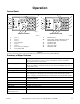
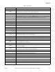
Summary of Control Outputs and
Inputs
Outputs
General outputs provide signals to operate the
following components.
1. Hot Fill Valve
2. Cold Fill Valve
3. Drain Valve (normally open)
4. Door Lock Solenoid Coil
5. Door Unlock Solenoid Coil
6. Supply 1 (detergent)
7. Supply 2 (bleach)
8. Supply 3 (sour/softener)
9. Optional 3rd (auxiliary) Fill Inlet (governed by
the configuration settings)
10. Optional Heat
11. *Prep for Card Reader or Central Pay (“machine
available signal”)
For standard models, the components for outputs
shown as “optional” will not be populated on the
output printed circuit board.
AC outputs are solid state outputs that operate either
120 Volt AC or 220 Volt AC (nominal voltage)
components, depending on the control voltage
configuration. Outputs are fused appropriately.
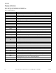
Inputs
1. Low Water Level
2. Medium Water Level
3. High Water Level
4. Door
5. Coin 1 Signal
6. Coin 2 Signal
7. *Prep for Card Reader or Central Pay (“start
pulse”)
* This allows machine to interface with the card reader or the
central pay system. “Start Pulse” originates from the reader/
central pay system, and this satisfies the programmed vend.
B control provides “Machine Available” signal to reader/
central pay when it is ready to accept payment. Refer to
Machine Electrical Schematic.
Control Voltage
The control power supply can be configured to operate
on 110 Volt AC nominal RMS input voltage
50/60 Hertz, OR 220 Volt AC nominal RMS input
voltage 50/60 Hertz.