Cabinet Hardmount Design 2 and 3 Models Refer to Page 8 for Model Identification Original Instructions Keep These Instructions for Future Reference. (If this machine changes ownership, this manual must accompany machine.) www.alliancelaundry.com Installation/Operation/Maintenance Washer-Extractors CHM1786C_SVG Part No.
Table of Contents Safety Information..................................................................................5 Explanation of Safety Messages....................................................................... 5 Important Safety Instructions........................................................................... 6 Safety Decals................................................................................................. 7 Operator Safety.....................................................
Connection Specifications..............................................................................50 Single-Phase Connections.......................................................................... 50 Three-Phase Connections........................................................................... 50 Grounding................................................................................................ 50 Phase Adder..................................................................................
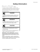
Safety Information Safety Information Explanation of Safety Messages Precautionary statements (“DANGER,” “WARNING,” and “CAUTION”), followed by specific instructions, are found in this manual and on machine decals. These precautions are intended for the personal safety of the operator, user, servicer, and those maintaining the machine. DANGER Indicates an imminently hazardous situation that, if not avoided, will cause severe personal injury or death.
Safety Information Important Safety Instructions • WARNING • To reduce the risk of fire, electric shock, serious injury or death to persons when using your washer, follow these basic precautions: W023 • • • • • • • • • Read all instructions before using the washer. Install the washer according the INSTALLATION instructions. Refer to the GROUNDING instructions in the INSTALLATION manual for the proper grounding of the washer.
Safety Information NOTE: The WARNINGS and IMPORTANT SAFETY INSTRUCTIONS appearing in this manual are not meant to cover all possible conditions and situations that may occur. Common sense, caution and care must be exercised when installing, maintaining, or operating the washer. Operator Safety WARNING NEVER insert hands or objects into basket until it has completely stopped. Doing so could result in serious injury.
Introduction Introduction Model Identification Information in this manual is applicable to Design 2 models or later. Refer to the 12th position of the model number (e.g.
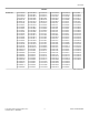
Introduction Models 30 POUND CCN030HNF CCN030HNV CCN030KNF CCN030KNV HCD030LDF HCD030LDV HCL030GNF HCL030HCF HCL030HDF HCL030HEF HCL030HLF HCL030HNF HCL030HNV HCL030KCV HCL030KDF HCL030KDV HCL030KEF HCL030KEV HCL030KXV HCL030KYF HCN030GNF HCN030GNV HCN030HCF HCN030HDF HCN030HEF HCN030HNF HCN030HNV HCN030HXF HCN030HYF HCN030KCF HCN030KCV HCN030KDF HCN030KDV HCN030KEF HCN030KEV HCN030KXF HCN030KYF HCN030KYV HCU030GNF HCU030GNV HCU030HLF HCU030HNF HCU030HNV HCU030HXF HCU030KCF HCU030KCV HCU030KEV HCU030KLV
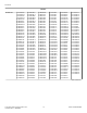
Introduction Models 40 POUND CCN040HNF CCN040HNV CCN040KNF CCN040KNV HCB040GNF HCB040HCF HCB040HNF HCB040HNV HCB040KCF HCB040KCV HCB040KEV HCB040KLV HCB040KXF HCB040KYF HCB040KYV HCB040LDF HCD040LDF HCD040LDV HCL040GNF HCL040GNV HCL040HCF HCL040HDF HCL040HEF HCL040HNF HCL040HNV HCL040KCV HCL040KDF HCL040KDV HCL040KEV HCL040KXV HCN040GNF HCN040GNV HCN040HCF HCN040HDF HCN040HEF HCN040HNF HCN040HNV HCN040HXF HCN040HYF HCN040KCF HCN040KCV HCN040KDF HCN040KDV HCN040KEF HCN040KEV HCN040KXF HCN040KYF HCN040KYV
Introduction Models 60 POUND CCN060HNF CCN060HNV CCN060KNF CCN060KNV HCD060LDF HCD060LDV HCL060GNF HCL060GNV HCL060HCF HCL060HDF HCL060HNF HCL060HNV HCL060KDF HCL060KDV HCL060KEV HCL060KXV HCN060GNF HCN060GNV HCN060HCF HCN060HDF HCN060HEF HCN060HNF HCN060HNV HCN060HXF HCN060HYF HCN060KCF HCN060KCV HCN060KDF HCN060KDV HCN060KEF HCN060KEV HCN060KXF HCN060KYF HCN060KYV HCU060GNF HCU060GNV HCU060HLF HCU060HNF HCU060HNV HCU060HXF HCU060KCF HCU060KCV HCU060KEV HCU060KLV HCU060KYF HCU060KYV ICN060GNF ICN060HNF
Introduction Models 100 POUND CCN100HNF CCN100HNV HCL100GNF HCL100HNV HCL100KDF HCL100KDV HCN100GNF HCN100HNV HCN100KCF HCN100KCV HCN100KDF HCN100KDV HCN100KEF HCN100KEV HCN100KXF HCN100KXV HCN100KYF HCN100KYV HCU100HNV ICN100GNF ICN100HNF ICN100HNV ICN100KCF ICN100KCV ICN100KDV ICN100KEV ICN100KNF ICN100KNV ICN100KXV ICN100KYV SCL100GNF SCL100KNV SCN100GNF SCN100JCF SCN100KNF SCN100KNV SCN100LCF SCN100LCV SCN100LDF SCN100LDV SCN100LEF SCN100LEV SCN100LXF SCN100LXV SCN100LYF SCN100LYV SCN100WCF SCN100W
Introduction Alliance Laundry Systems Shepard Street P.O. Box 990 Ripon, WI 54971-0990 U.S.A. www.alliancelaundry.com Phone: +1 (920) 748-3121 Ripon, Wisconsin Alliance International: +32 56 41 20 54 Wevelgem, Belgium © Copyright, Alliance Laundry Systems LLC - DO NOT COPY or TRANSMIT 13 Part No.
Specifications and Dimensions Specifications and Dimensions General Specifications Specification 20 30 40 60 80 100 Overall Dimensions Overall width, in. [mm] 26.0 [660] Overall height, in [mm] Design 2 Design 3 Overall depth, in. [mm] 29.0 [737] 42.0 [1067] 44.95 [1142] 43.0 [1092] 30.63 [778] 34.06 [865] 41.5 [1054] 41.5 [1054] 47.2 [1199] 49.89 [1267] 56.16 [1426] 56.16 [1426] 30.85 [784] 35.29 [896] 42.25 [1073] 4.7 [1135] 48.6 [1234] 52.6 [1336] Net weight, lbs.
Specifications and Dimensions Specification 20 30 40 60 80 100 Perforation size, in. [mm] 0.188 [4.78] 0.188 [4.78] 0.188 [4.78] 0.188 [4.78] 0.188 [4.78] 0.188 [4.78] Perforation open area, % 17.3 18.6 18.8 18.8 19.6 20.2 11.6 [295] 14.3 [363] 16.3 [414] 16.3 [414] 18.5 [470] 18.5 [470] Height of door bottom above floor, in. 14.38 [365] [mm] 14 [356] 14.56 [370] 14.94 [379] 17.91 [455] 17.91 [455] Height of door opening above floor, in. [mm] 17 [432] 17 [431] 17.
Specifications and Dimensions Specification Average steam consumption per cycle, bHP 20 30 40 60 80 100 .34 .41 .78 .98 1.34 1.58 200V 5.4 5.4 10.8 10.8 19.1 19.1 240V 7.8 7.8 15.6 15.6 27.4 27.4 380V 6.5 6.5 13.0 13.0 17.2 17.2 415V 7.8 7.8 15.5 15.5 20.5 20.5 480V N/A N/A 15.6 15.6 27.4 27.4 Electrical heating elements 3 3 6 6 6 6 Electrical heat element size, kW 2.6 2.6 2.6 2.6 4.2 4.
Specifications and Dimensions Machine Dimensions 20-60 Pound Capacity Machines 20-60 Pound Models K J I H G 3 F 4 1 Q 5 2 W L A B C V D R S M 6 E 1. 2. 3. 4. 5. 6. T U N O P CHM2434N_SVG Supply Dispenser Input Power Block Compartment Hot Water Inlet Cold Water Inlet Vacuum Breaker Drain Outlet Figure 2 Machine Capacity Dimensions - 20-60 Pound Models, in. [mm] Specification 20 20 (Design 2) (Design 3) 30 40 60 A 38.0 [965] 39.0 [991] 40.94 [1040] 43.19 [1097] 45.88 [11.
Specifications and Dimensions Machine Capacity Dimensions - 20-60 Pound Models, in. [mm] Specification 20 20 (Design 2) (Design 3) 30 40 60 E 7.83 [199] 7.83 [199] 9.33 [237] 8.82 [224] 9.89 [251] F 2.99 [76] 2.99 [76] 2.99 [76] 2.99 [76] 2.99 [76] G 6.94 [176] 6.94 [176] 6.94 [176] 6.94 [176] 6.94 [176] H 8.82 [224] 8.82 [224] 8.82 [224] 8.82 [224] 8.82 [224] I 15.15 [385] 15.15 [385] 15.15 [385] 15.15 [385] 19.9 [505] J 15.65 [398] 15.65 [398] 15.65 [398] 15.
Specifications and Dimensions 80 and 100 Pound Capacity Machines 80 and 100 Pound Models M L K J I H 3 4 G 2 1 S 5 6 F AA 7 A B C Z N T D U 8 E V O Y P X Q W R CHM2435N_SVG 1. 2. 3. 4. 5. 6. 7. 8. Supply Dispenser Input Power Block Compartment Auxiliary Hot Water Inlet Auxiliary Cold Water Inlet Cold Water Inlet Hot Water Inlet Vacuum Breaker Drain Outlet Figure 3 Machine Capacity Dimensions - 80 and 100 Pound Models, in. [mm] A 51.82 [1316] O 1.36 [35] B 50.32 [1278] P 39.
Specifications and Dimensions Machine Capacity Dimensions - 80 and 100 Pound Models, in. [mm] D 6.41 [163] R 80 48.6 [1234] 100 52.6 [1336] E 2.55 [65] S 9.0 [229] F 2.99 [76] T 30.91 [785] G 6.94 [176] U 20.77 [528] H 8.82 [224] V 17.91 [455] I 16.66 [423] W 41.5 [1054] J 18.18 [462] X 26.15 [664] K 21.65 [550] Y 3.57 [91] L 26.15 [664] Z 56.16 [1426] M 30.35 [771] AA 1.5 [38] N 53.
Specifications and Dimensions Mounting Bolt Hole Locations – 20 and 30 Pound Models 20 and 30 Pound Models (refer to Table 4 ) B D C E A G I H F J K L P M N O 1 Q 2 3 R CHM2395N_SVG 1. Elevated Base Width 2. Front of Base 3. Machine Width Figure 4 Mounting Bolt Hole Locations – 20 and 30 Pound Models, in. [mm] Specification 20 30 A 2 [51] 2 [51] B 26.37 [670] 29.38 [746] C 20.88 [530] 23.89 [607] Table 4 continues...
Specifications and Dimensions Mounting Bolt Hole Locations – 20 and 30 Pound Models, in. [mm] Specification 20 30 D 2.75 [70] 2.75 [70] E 0.18 [5] 0.18 [5] F 0.25 [6] 0.25 [6] G 0.64 [16] 0.64 [16] H 2.71 [69] 2.37 [60] I 2.15 [55] 1.81 [46] J 4.69 [119] 4.69 [119] K 0.19 [5] 0.19 [5] L 9.64 [245] 10.5 [267] M 23.94 [608] 28.94 [735] N 24.69 [627] 29.69 [754] O 27.92 [709] 32.59 [828] P 20.65 [524] 23.5 [597] Q 26.37 [670] 29.38 [746] R 26 [660] 29.
Specifications and Dimensions Mounting Bolt Hole Locations - 40 and 60 Pound Models 40 and 60 Pound Models (refer to Table 5 ) B D C E A F H G I K J O M L N 1 P 2 3 Q CHM2397N_SVG 1. Elevated Base Width 2. Front of Base 3. Machine Width Figure 5 Mounting Bolt Hole Locations - 40 and 60 Pound Models, in. [mm] Specification A 40 60 2 [51] 2 [51] Table 5 continues... © Copyright, Alliance Laundry Systems LLC - DO NOT COPY or TRANSMIT 23 Part No.
Specifications and Dimensions Mounting Bolt Hole Locations - 40 and 60 Pound Models, in. [mm] Specification 40 60 B 30.88 [784] 34.44 [875] C 26 [660] 30 [762] D 2.44 [62] 2.22 [56] E 0.12 [3] 0.12 [3] F 0.64 [16] 0.64 [16] G 2.37 [60] 2.37 [60] H 2 [51] 1.75 [44] I 4.75 [121] 5.15 [131] J 1.19 [30] 1.25 [32] K 12.5 [318] 11.93 [303] L 32.5 [826] 36 [914] M 33.54 [852] 36.87 [936] N 37.25 [946] 40.5 [1029] O 23.63 [600] 27.5 [699] P 30.88 [784] 34.
Specifications and Dimensions Mounting Bolt Hole Locations – 80 and 100 Pound Models 80 and 100 Pound Models (refer to Table 6 ) A D E F B C N G A B B O A H P A B I B A Q J R K L A B B A M CHM2399N_SVG NOTE: For single machine installations or two machines installed back to back, use the outside bolt holes marked “A”. For multiple machines installed side by side with minimum clearance, use the inside bolt holes marked “B”.
Specifications and Dimensions Mounting Bolt Hole Locations – 80 and 100 Pound Models, in. [mm] Specification 80 100 D .94 [24] .94 [24] E 4.94 [124] 4.94 [124] F 6.63 [164] 6.63 [164] G 3.3 [84] 3.3 [84] H 16 [406] 16 [406] I 35 [889] 35 [889] J 37.3 [947] 37.3 [947] K 42.2 [1073] N/A L N/A 46.2 [1260] M 1 [25] 1 [25] N 1.96 [50] 1.96 [50] O Outside 42.72 [1085] 35.43 [900] P Inside 52.86 [1342] 47.16 [1197] Q Outside 35.43 [900] 42.72 [1085] R Inside 47.
Specifications and Dimensions Floor Mounting Layout – 20-60 Pound Models Dimensional Clearances - Single Machine Mount (refer to Table 7 ) 1 A 2 B C 4 3 C B 5 1. 2. 3. 4. 5. CHM2426N_SVG Wall Rear of Base Edge of Concrete Pad Machine 1 Front of Base Figure 7 Dimensional Clearances - Single Machine Mount - 20-60 Pound Models, in. [mm] Description 20 30 40 60 A Distance to wall (minimum) 24 [610] 24 [610] 24 [610] 24 [610] B Distance of machine base to edge of pad (minimum) 3.
Specifications and Dimensions Dimensional Clearances - Side-by-Side Mount (refer to Table 8 ) 1 A 2 2 2 3 4 5 3 6 B B 6 6 CHM2375N_SVG 1. 2. 3. 4. 5. 6. Wall Rear of Base Machine 1 Machine 2 Machine 3 Front of Base Figure 8 Dimensional Clearances - Side-by-Side Mount - 20-60 Pound Models, in. [mm] Description A Distance to wall (minimum) B 20 24 [610] 30 40 60 24 [610] 24 [610] 24 [610] Mounted without bases (min- 5.14 [131] imum) 5.12 [130] 4.63 [118] 4.
Specifications and Dimensions Dimensional Clearances - Back-to-Back Mount (refer to Table 9 ) 1 B 2 3 5 A 3 4 1 B CHM2376N_SVG 1. 2. 3. 4. 5. Front of Machine Machine 2 Rear of Machine Machine 1 Edge of Concrete Pad Figure 9 Dimensional Clearances - Back-to-Back Mount - 20-60 Pound Models, in. [mm] Description 20 30 40 60 A Adjacent rear bolt spacing (minimum) 28.3 [719] 27.6 [702] 28.0 [710] 27.5 [699] B Distance from front bolt to edge of pad (minimum) 5.26 [134] 5.26 [134] 6.
Specifications and Dimensions Floor Mounting Layout – 80 and 100 Pound Models Standard Mount for Single Machine (refer to Table 10 ) 1 A 2 B C 4 3 C B 5 1. 2. 3. 4. 5. CHM2427N_SVG Wall Rear of Base Edge of Concrete Pad Machine 1 Front of Base Figure 10 Standard Mount for Single Machine - 80 and 100 Pound Models, in. [mm] Description 80-100 A Distance to wall (minimum) 24 [610] B Distance of machine base to edge of pad (minimum) 4.
Specifications and Dimensions Standard Mount Side-by-Side (refer to Table 11 ) 1 A 2 2 3 4 5 1. 2. 3. 4. 5. B 5 PHM819N_SVG Wall Rear of Base Machine 1 Machine 2 Front of Base Figure 11 Standard Mount Side-by-Side - 80 and 100 Pound Models, in. [mm] Description 80-100 A Distance to wall (minimum) 24 [610] B Adjacent unit bolt spacing (minimum) 6 [152] Table 11 © Copyright, Alliance Laundry Systems LLC - DO NOT COPY or TRANSMIT 31 Part No.
Specifications and Dimensions Close Mount Side-by-Side (refer to Table 12 ) 1 A 2 2 3 4 5 1. 2. 3. 4. 5. B 5 PHM820N_SVG Wall Rear of Base Machine 1 Machine 2 Front of Base Figure 12 Close Mount Side-by-Side - 80 and 100 Pound Models, in. [mm] Description 80-100 A Distance to wall (minimum) 24 [610] B Adjacent unit bolt spacing (minimum) 10.38 [264] IMPORTANT: When close mounting, bolt machine using inside bolt holes.
Specifications and Dimensions Back-to-Back Mount (refer to Table 13 ) 1 B 2 3 A 5 3 4 1 B PHM810N_SVG 1. 2. 3. 4. 5. Front of Machine Machine 2 Rear of Machine Machine 1 Edge of Concrete Pad Figure 13 © Copyright, Alliance Laundry Systems LLC - DO NOT COPY or TRANSMIT 33 Part No.
Specifications and Dimensions Back-to-Back Mount - 80 and 100 Pound Models, in. [mm] Description 80-100 A Adjacent rear bolt spacing (minimum) 33.3 [846] B Distance from front bolt to edge of pad (minimum) 8 [203] Table 13 © Copyright, Alliance Laundry Systems LLC - DO NOT COPY or TRANSMIT 34 Part No.
Installation Installation Pallet Jack Cover Plate Removal (80 and 100 Pound Models Only) Prior to installing an 80 and 100 pound machine, the optional pallet jack cover plate can be removed in preparation of re-installing to machine base frame after machine installation. 1. Locate cover plate on back panel. 2. Remove back panel. 3. Remove all hardware holding cover plate on back panel, refer to Figure 14 . DO NOT DISCARD HARDWARE. 4. Remove cover plate.
Installation CHM2412N_SVG Figure 15 New Foundation If the existing floor slab does not meet the single machine foundation requirements per model, refer to Figure 18 and proceed to Machine Foundation and Pad Installation section. Isolated Pad Installation This type of installation is NOT recommended. Installer MUST consult a Structural Engineer for concrete specifications and requirements for installations that will not be tied into adjacent foundations.
Installation Machine Foundation and Pad Installation ted by the machine during extract. This concrete pad, recommended not to exceed 8 inches [203 mm] above existing floor, must be placed, reinforced with rebar and tied to the existing floor. Refer to Table 14 , Figure 16 , Figure 17 and Figure 18 for multiple machine installations. A concrete pad may be constructed to elevate a machine. Care must be exercised in the design of the pad due to the force exer- Machine Foundation and Pad Installation, in.
Installation 14. Proceed to Machine Mounting and Grouting section. © Copyright, Alliance Laundry Systems LLC - DO NOT COPY or TRANSMIT 38 Part No.
Installation Machine Installation Existing Floor (refer to Table 15) 1 A 2 PHM814N_SVG 1. Existing Floor with 3500 PSI (minimum) Concrete 2. Compacted Fill (minimum 6 in. [152 mm]) Figure 16 Existing Floor, in. [mm] Description A Required thickness of existing floor (minimum) 20-30 4 [102] 40-60 (F-speed) 4 [102] 40-60 (V-speed) 6 [152] 80-100 9 [229] Table 15 Elevated Pad (refer to Table 16) 2 B C 3 1 A 4 D 5 E PHM852N_SVG 1. 2. 3. 4. 5.
Installation Elevated Pad, in. [mm] Description 20-30 40-60 (F-speed) 40-60 (V-speed) 80-100 A Height of elevated pad above floor (maximum) 8 [203] 8 [203] 8 [203] 8 [203] B Distance between reinforcing bars (maximum) 12 [305] 12 [305] 12 [305] 12 [305] C Length of reinforcing bar extending in- 2.5 [64] to existing floor (minimum) 2.5 [64] 2.5 [64] 2.5 [64] D Total depth of foundation (concrete plus 6 in.
Installation Tie-in to Existing Floor, in. [mm] Description 40-60 (F-speed) 20-30 40-60 (V-speed) 80-100 B Total depth of foundation (concrete plus 6 in. [152 mm] fill)(minimum) 8 [203] 8 [203] 12 [305] 15 [381] C Distance between reinforcing bars (minimum) 12 [305] 12 [305] 12 [305] 12 [305] D Length of reinforcing bar extending in- 2.5 [64] to existing floor (minimum) 2.5 [64] 2.5 [64] 2.
Installation 17. Hand tighten each nut. a. Tighten the two rear nuts two turns. b. Tighten the two front nuts two turns. c. Tighten the two middle nuts firmly. 18. Torque all the locknuts to 90 ± 9 ft.-lbs. – one after the other – until all are tightened evenly and the machine is fastened securely to the elevated base frame or floor. 80 Pound and Larger Models 19. After the grout is completely cured, torque the locknuts to 150 ± 15 ft.-lbs.
Installation Cast-in-place Anchors (refer to Table 18 ) B C 1 2 A 3 D 4 5 1. 2. 3. 4. 5. E CHM2438N_SVG Machine Frame Base Grout Anchor Bolt (minimum Grade 5 SAE rating) Concrete Edge of Pad Figure 20 Minimum Anchoring Specifications, in. [mm] Description 20-40 60 80-100 Number of Bolts 4 or 6* 6 6 A Bolt Length 6 [152] 6 [152] 8.75 [216] B Thread Extension 2.5 [64] 2.5 [64] 2.75 [64] C Bolt Diameter 5/8 [16] 5/8 [16] 3/4 [19] D Embedment Depth 3.5 [89] 3.
Installation Floor Load Data Specification 20 30 40 60 80 100 Dynamic floor load, lbs. [kN] 420 [1.86] 630 [2.80] 840 [3.74] 1260 [5.61] 1680 [7.48] 1680 [7.48] Dynamic floor pressure, lbs.ft2 [kN-m2] 96 [4.60] 109 [5.22] 119 [5.70] 143 [6.85] 149 [7.13] 149 [7.13] Dynamic load frequency, Hz F-speed 9.7 9.0 8.6 8.1 7.4 7.4 V-speed 13.7 12.8 12.2 11.4 10.4 9.5 Maximum moment about machine base, lbs.-ft. [kN-m] 805 [1.09] 1260 [1.71] 1820 [2.47] 2770 [3.76] 4330 [5.
Installation Drain Trough System 1 2 3 7 5 6 4 CHM2379N_SVG 1. 2. 3. 4. 5. 6. 7. Rear of Machine Drain Pipe Steel Grate Drain Trough Strainer Waste Line 1 in. [25 mm] minimum gap Figure 21 Direct Drain System 4 5* 3 2 1 6 CHM2386N_SVG * Drain line must be vented to meet local plumbing codes. 1. 2. 3. 4. 5. 6. Drain Hose Drain Valve Drain Tee Overflow Hose Vent Pipe* Trap (as required by local codes) Figure 22 © Copyright, Alliance Laundry Systems LLC - DO NOT COPY or TRANSMIT 45 Part No.
Installation IMPORTANT: Increasing the drain hose length, installing elbows, or causing bends will decrease drain flow rates and increase drain times, impairing machine performance. NOTE: Installation of additional machines will require larger drain connections. Refer to Drain Line Sizing / Minimum Drain ID . Drain Information Specification 20 30 40 60 80 100 Drain connection size, in. [mm] 2 [51] 2 [51] 3 [76]* 3 [76]* 3 [76]* 3 [76]* Overflow drain connection size, in. [mm] 1.5 [457] 1.
Installation 2. Check filters in the machine’s inlet hoses for proper fit and cleanliness before connecting. 3. Hang hoses in a large loop; do not allow them to kink. If additional hose lengths are needed or using hoses other than those supplied by manufacturer, flexible hoses with screen filters are required. Cabinet Hardmount Water Supply Information Specification Requirement Model Water Inlet Connection size, in. BSP [mm] 20-100 3/4 [19] Thread pitch, GHT [BSPP] 20-100 3/4 x 11.
Installation on the serial plate on the rear of the machine, using copper conductors only. IMPORTANT: Alliance Laundry Systems warranty does not cover components that fail as a result of improper input voltage. Make sure the correct transformer jumper (208 Volt or 240 Volt) is in place. Refer to the “optional” Electrical Service Conversion label located on the back of the machine near the serial plate. Refer to Figure 26 .
Installation Input Power Conditioning install one of the devices listed under the Possible Corrective Action(s). The drive is suitable for direct connection to input power within the rated voltage of the drive. Listed in Input Power Condition are certain input power conditions which may cause component damage or reduction in product life. If any of the conditions exist, IMPORTANT: Only one device per branch circuit is required.
Installation Connection Specifications 2 3 IMPORTANT: Connection must be made by a qualified electrician using wiring diagram provided with machine, or according to accepted European Union standards. 1 Connect machine to an individual branch circuit not shared with lighting or other equipment. Shield connection in a liquid-tight or approved flexible conduit. Copper conductors of correct size must be installed in accordance with National Electric Code (NEC) or other applicable codes.
Installation Machines with Electric Heat 2 3 CHASIS L1 L2 L3 TB1 SERVICE GROUND 1 CHM2380N_SVG 1. Grounding Lug: Connect to proven earth ground 2. Customer Input Power Terminals 3. Internal Load Distribution - DO NOT connect customer power source or load. Figure 29 Machines without Electric Heat 2 CHASIS 1 TB1 SERVICE GROUND CHM2381N_SVG 1. Grounding Lug: Connect to proven earth ground 2.
Installation North American Approval 20 Pound Capacity Models (North American Approval) Voltage Designation Code Voltage Specifications Cycle Phase Full Load Amps Wire Circuit Breaker AWG mm2 F and V-Speed Models (unless otherwise noted) B (F-speed) 120 60 1 2 7 15 14 2.5 B (V-speed) 120 60 1 2 8 15 14 2.5 X 200-208 50/60 1/3 2/3 4/3 15 14 2.5 50/60 3 3 3 15 14 2.5 21 30 10 6.
Installation 30 Pound Capacity Models (North American Approval) Voltage Designation Code Q Standard 200–208 Electric Heat 220-240 N P Voltage Standard Specifications Cycle 50/60 Phase 3 Full Load Amps Wire 3 Circuit Breaker AWG mm2 4 15 14 2.5 22 30 10 6.0 440–480 50/60 3 3 3 15 14 2.5 380–415 50/60 3 3 3 15 14 2.5 13 15 14 2.5 Electric Heat NOTE: Wire sizes shown are for copper, THHN, 90°C conductor per NEC article 310.
Installation 40 Pound Capacity Models (North American Approval) Voltage Designation Code P Standard Voltage 380–415 Specifications Cycle 50/60 Phase 3 Full Load Amps Wire 3 Electric Heat Circuit Breaker AWG mm2 3 15 14 2.5 25 30 10 6.0 NOTE: Wire sizes shown are for copper, THHN, 90°C conductor per NEC article 310.
Installation 80 Pound Capacity Models (North American Approval) Voltage Designation Code Voltage Specifications Cycle Phase Full Load Amps Wire Circuit Breaker AWG mm2 F-Speed Models X 200–208 50/60 1/3 2/3 12/8 15 14 2.5 50/60 3 3 8 15 14 2.5 72 80 4 25.0 5 15 14 2.5 37 40 8 10.0 5 15 14 2.5 33 40 8 10.
Installation 100 Pound Capacity Models (North American Approval) Voltage Designation Code Voltage Specifications Cycle Phase Full Load Amps Wire Circuit Breaker AWG mm2 F-Speed Models X 200-208 50/60 1/3 2/3 16/9 20/15 12/14 4/2.5 50/60 3 3 9 15 14 2.5 74 80 4 25.0 6 15 14 2.5 37 40 8 10.0 6 15 14 2.5 34 40 8 10.
Installation CE Approval 20 Pound Capacity Models (CE Approval) Voltage Designation Code Voltage Specifications Cycle Phase Full Load Amps Wire Circuit Breaker mm2 F and V-Speed Models N 440-480 50/60 3 3 2 6 2.5 X 200–208 50/60 1/3 2/3 4/3 6 2.5 50/60 3 3 3 6 2.5 21 25 2.5 2 6 2.5 13 16 2.
Installation 30 Pound Capacity Models (CE Approval) Voltage Designation Code Voltage Specifications Cycle Phase Full Load Amps Wire Circuit Breaker mm2 NOTE: Wire sizes shown are for copper, THHN, 90°C conductor per NEC article 310.
Installation 60 Pound Capacity Models (CE Approval) Voltage Designation Code Voltage Specifications Cycle Phase Full Load Amps Wire Circuit Breaker mm2 F and V-Speed Models (unless otherwise noted) N Standard 440-480 50/60 3 3 Electric Heat X 200–208 4 6 2.5 22 25 2.5 50/60 1/3 2/3 11/7 16/10 2.5 50/60 3 3 7 10 2.5 43 50 10.0 4 6 2.5 26 32 2.5 4 6 2.5 26 32 2.
Installation 80 Pound Capacity Models (CE Approval) Voltage Designation Code P Voltage Standard 380-415 Specifications Cycle 50/60 Phase 3 Full Load Amps Wire 3 Electric Heat Circuit Breaker mm2 7 10 2.5 33 40 4.0 7 10 2.5 37 40 4.0 V-Speed Models N Standard 440-480 50/60 3 3 Electric Heat X 200–208 50/60 1/3 2/3 17/11 20/16 2.5 50/60 3 3 11 16 2.5 72 80 16.0 7 10 2.5 33 40 4.
Installation 100 Pound Capacity Models (CE Approval) Voltage Designation Code P Voltage Standard 380-415 Specifications Cycle 50/60 Phase 3 Full Load Amps Wire 3 Electric Heat Circuit Breaker mm2 7 10 2.5 34 40 4.0 NOTE: Wire sizes shown are for copper, THHN, 90°C conductor per NEC article 310. Table 36 © Copyright, Alliance Laundry Systems LLC - DO NOT COPY or TRANSMIT 61 Part No.
Installation Steam Requirements (Steam Heat Option Only) Supply Dispensing WARNING Hot Surfaces. Will cause severe burns. Turn steam off and allow steam pipes, connections and components to cool before touching. W505 For machines equipped with optional steam heat, install piping in accordance with approved commercial steam practices. Steam requirements are shown in Table 37 . Steam Supply Information Steam inlet connec- 40–100 pound* tion size, in. [mm] 1/2 [13] Number of steam inlets 1 80 [5.
Installation IMPORTANT: DO NOT remove the red jumper wire from the terminal strip. There are 3 terminals necessary for this connection option. • 1 • EXTERNAL DISPENSER CONNECTIONS ES 1 EXAMPLE FOR EXTERNAL DISPENSER CONNECTION ES 2 ES 3 ES 4 RELAY COM Supply 1 External Dispensing System RELAY COM 24VAC COM IMPORTANT: Do not use the transformer terminals if an external power supply is used.
Installation 3 2 4 1 5 6 7 = Neutral = Power PHM821N_SVG 1. 2. 3. 4. 5. 6. 7. External Supply Power Output Internal Control Transformer RELAY COM Terminal External Dispenser Input Signal Common Red Jumper Wire 24VAC Terminal 24VAC COM Terminal Figure 32 Chemical Injection Using External AC Power Source NOTE: An External AC Power Source is NOT provided by Alliance Laundry Systems. NOTE: Power for external supplies must not be derived from the high-voltage main power connection point. 1.
Installation 3 1 4 2 = Neutral = Power 5 PHM823N_SVG 1. 2. 3. 4. 5. External Supply Power Output Red Jumper Wire External Supply Input Signal Common VAC Power Terminal VAC RETURN Terminal Figure 33 External Supply Signals CAUTION Do not attempt to increase fuse rating or alter wiring of external chemical supply terminal strip in such as way that may conflict with the suggested methods provided on the Optional External Supply Wiring Diagram.
Installation 3 = Neutral = Power 1 2 PHM822N_SVG 1. ES1 Power supply 2. K1 Contact 3. Supply 1 Signal Figure 34 3 = Neutral = Power 1 2 PHM824N_SVG 1. ES1 Power supply 2. K1 Contact 3. Supply 1 Signal Figure 35 © Copyright, Alliance Laundry Systems LLC - DO NOT COPY or TRANSMIT 66 Part No.
Installation Connection of External Liquid Supplies OPL Models 1. Facing the rear of the machine, locate the five (5) 3/8 inch [10 mm] supply hose connections found on the right-hand side of the valve panel. Refer to Figure 36 . Valve Panel-Rear View 1 CHM2388N_SVG 1. External Supply Hose Opening Figure 36 2. Drill through the five (5) plastic holes on the valve panel for the external supply hoses as needed. 3. Remove plastic debris. 4.
Start Up Start Up Pallet Jack cover Plate Installation (80 and 100 Pound Models Only) After machine is fully installed, the optional pallet jack cover plate can be installed. 1. Locate the two holes on the front of the machine base frame. Refer to Figure 37 . 4 1 3 2 1 CHM2392N_SVG 1. 2. 3. 4. Nut Cover Plate Stud Machine Base Frame Figure 37 2. Using the hardware from removing plate from back panel, install the cover plate to the machine base frame.
Operation Operation Operating Instructions 5. The default wash cycle will display. WARNING 1. Turn on main power source (circuit breaker). 2. Turn handle clockwise to open. Refer to Figure 38 . To prevent personal injury, avoid contact with inlet water temperatures higher than 125° Fahrenheit [51° Celsius] and hot surfaces. W748 6. Select the desired soil setting (select models only), cycle setting (select models only) and cycle/temperature. The LED indicator(s) for that cycle will light.
Operation a. DETERGENT 1 2 CHM2227N_SVG CHM2228N_SVG 1. Liquid Detergent 2. Powder Detergent b. BLEACH 3 4 CHM2229N_SVG 3. Liquid Bleach CHM2230N_SVG 4. Powder Bleach c. SOFTENER 5 CHM2231N_SVG 5. Liquid Softener Table 39 © Copyright, Alliance Laundry Systems LLC - DO NOT COPY or TRANSMIT 70 Part No.
Maintenance Maintenance Maintenance 4. Inspect all chemical inlets, lines and connections for leaks. WARNING WARNING To reduce the risk of electrical shock, serious injury or death, disconnect the electrical power to washer-extractor before examining the wiring. Sharp edges can cause personal injury. Wear safety glasses and gloves, use proper tools and provide lighting when handling sheet metal parts. W366R1 IMPORTANT: Replace all panels that are removed to perform service and maintenance procedures.
Maintenance IMPORTANT: The control module cover and fan filter must be in place for the fan to properly cool the inverter drive. Failure to observe this warning will void the warranty and could lead to expensive inverter drive repair. 3. On machines equipped with an automatic chemical supply system, check chemical connections by inspecting all connections and chemical hoses for leaks or cracks. 1 2 5 IMPORTANT: Chemical leaks can quickly cause permanent damage to the machine components and structure.
Maintenance Belt Tension by Frequency or Belt Tension Gauge Model 1 Frequency (Hz) Belt Tension (lbs.) Tension Gauge (N) 20 (1 HP) 95 ± 2 39.6 ± 1.5 176 ± 7 20 98 ± 2 (2 HP)* 70.2 ± 5.6 312 ± 25 30* 99 ± 4 71 ± 5.6 317 ± 25 40* 87 ± 84 70.3 ± 6.3 313 ± 28 60* 87 ± 4 92.7 ± 8.8 413 ± 39 80-100 102 ± 2 132 ± 5 588 ± 23 * Models made before 10/13/14 are self-tensioning and do not require any adjustment. CHM2437N_SVG 1. 1/4 inch [6.
Maintenance 5. Clean customer-supplied steam filter, where applicable. Refer to Figure 43 . a. Turn off steam supply and allow time for the valve to cool. b. Unscrew cap. c. Remove element and clean. d. Replace element and cap. 1 2 H042I_SVG 1. Cap 2. Steam Filter Element Figure 43 6. Check the bearing mounting bolts to make sure they are torqued properly. Refer to Torque . Torque, ft-lbs. Model Bearing Torque 20 All 41 30-40 All 101 60 All 201 80-100 All 357 Table 43 7.
Maintenance Care of Stainless Steel • • • • • • • • Remove dirt and grease with detergent and water. Thoroughly rinse and dry after washing. Avoid contact with dissimilar metals to prevent galvanic corrosion when salty or acidic solutions are present. Do not allow salty or acidic solutions to evaporate and dry on stainless steel. Wipe clean of any residues. Rub in the direction of the polish lines or “grain” of the stainless steel to avoid scratch marks when using abrasive cleaners.
Disposal of Unit Disposal of Unit This appliance is marked according to the European directive 2002/96/EC on Waste Electrical and Electronic Equipment (WEEE). This symbol on the product or on its packaging indicates that this product shall not be treated as household waste. Refer to Figure 44 . Instead it shall be handed over to the applicable collection point for the recycling of electrical and electronic equipment.