
Specifications


© Copyright, Alliance Laundry Systems LLC - DO NOT COPY or TRANSMIT
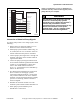
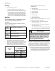
Specifications and Dimensions
39
C003292ENR1
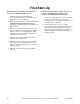
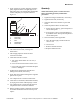
Figure 19
Connection of Chemical Pump Signals
To connect pump control to AC voltage signals, do the
following:
1. Remove large rear electrical module cover on
machine to access chemical terminals.
2. Mount pump system interface module using 7/8
in. (22 mm) hole in cover so that box will be on
outside of machine when panel is reinstalled.
3. Connect pump system signal wires 1 through 6 to
terminals 1 through 6 on the machine chemical
signal terminal block.
4. Connect all pump system signal common wires
to two machine chemical signal terminals labeled
“COM” (it is recommended to connect three
wires to each COM terminal as drawn in
Figure 19 – each terminal can accommodate up
to three 16 AWG wires).
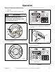
5. If a chemical timer hold function is being used
(this is common on solid supply systems
connected to multiple machines), connect hold
relay common terminal to one of two “HOLD”
terminals. Connect chemical hold relay normally
open wire to remaining “HOLD” terminal as
shown in diagram.
6. Reinstall rear electrical module cover with
chemical system interface module mounted on it.
7. Finish pump system installation per its
manufacturer’s instructions.
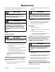
NOTE: Consult factory service or distributor for
assistance with dry contact format signals (to drive
pumps directly, for example).
PHM691N
HOLD
HOLD RELAY COM
HOLD RELAY NO
SIGNAL 6 COM
SIGNAL 6
SIGNAL 5 COM
SIGNAL 5
SIGNAL 4 COM
SIGNAL 4
SIGNAL 3 COM
SIGNAL 3
SIGNAL 2 COM
SIGNAL 2
SIGNAL 1 COM
SIGNAL 1
PUMP SYSTEM
INTERFACE MODULE
HOLD
COM
COM
6
5
4
3
2
1
This machine is not designed to provide
power for a chemical pump system!
Connecting such a load to the machine’s
controls may overload the control
transformer! Never connect power for any
device to the machine’s main power
terminal block – this is a violation of the
NEC and other electrical regulations.
W692
WARNING