
Specifications


© Copyright, Alliance Laundry Systems LLC - DO NOT COPY or TRANSMIT
Specifications and Dimensions
31
C003292ENR1
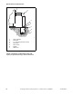
Drain Connection Requirements
A flexible connection must be made to a vented drain
system to prevent an air lock and to prevent siphoning.
IMPORTANT: Machines must be installed in
accordance with all local codes and ordinances.
IMPORTANT: The top of the vent must be 12
inches (304.8 mm) lower than bottom of inlet
valves.
If proper drain size is not available or practical, a surge
tank is required. A surge tank along with a sump pump
should be used when gravity drainage is not possible.
Increasing drain hose length, installing elbows or
causing bends will decrease drain flow rate and
increase drain times, impairing machine performance.
Drain Information
Specifications
IPH40
IPM40
IPH60
IPM60
IPH80
IPM80
IPH100
IPM100
IPH125
IPH140
IPM140
IPH175
Overflow Size,
in. (mm)
1.5
(38.1)
1.5
(38.1)
1.5
(38.1)
1.5
(38.1)
3
(76.2)
3
(76.2)
3
(76.2)
Drain connection size, I.D.,
in. (mm) with second drain
2
(50.8)
3
(76.2)
3
(76.2)
3
(76.2)
3
(76.2)
3
(76.2)
3
(76.2)
Number of drain outlets*
1111111
Drain flow capacity,
gal/min. (l/min.)
30
(114)
70
(265)
60
(227)
65
(246)
125
(473)
125
(473)
125
(473)
Recommended drain pit
size, ft3 (l) †
5
(142)
12
(340)
9
(255)
11
(311)
36
(1019)
36
(1019)
36
(1019)
†Sized for one machine using high level.
*Data reflects single drain, dual drain is optional.
Table 14