Pocket Hardmount Variable-Speed Refer to Page 6 for Model Identification PHM1397C PHM1397C Original Instructions Keep These Instructions for Future Reference. (If this machine changes ownership, this manual must accompany machine.) www.alliancelaundry.com Part No.
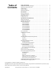
Table of Contents Safety Information.............................................................................. Explanation of Safety Messages........................................................... Important Safety Instructions ............................................................... Safety Decals ........................................................................................ Operator Safety.....................................................................................
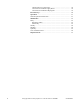
Chemical Service Connections ........................................................ 38 Connection of Chemical Supply Hoses ........................................... 38 Connection of Chemical Pump Signals ........................................... 39 First Start-Up ...................................................................................... 40 Operation............................................................................................. 41 General Operation Instructions................
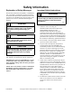
Safety Information Explanation of Safety Messages Precautionary statements (“DANGER,” “WARNING,” and “CAUTION”), followed by specific instructions, are found in this manual and on machine decals. These precautions are intended for the personal safety of the operator, user, servicer, and those maintaining the machine. DANGER DANGER indicates an imminently hazardous situation that, if not avoided, will cause severe personal injury or death.
Safety Information 7. Do not allow children to play on or in the washer. Close supervision of children is necessary when the washer is used near children. This appliance is not intended for use by young children or infirm persons without supervision. Young children should be supervised to ensure that they do not play with the appliance. This is a safety rule for all appliances. 8. DO NOT reach and/or climb into the tub or onto the washer, ESPECIALLY if the wash drum is moving.
Safety Information Operator Safety WARNING Machine installations must comply with minimum specifications and requirements stated in the applicable Installation Manual, any applicable municipal building codes, water supply requirements, electrical wiring regulations and any other relevant statutory regulations.
Safety Information Model Identification Information in this manual is applicable to these models: 40 Pound 60 Pound 80 Pound 100 Pound CP040PMN1 CP040PMQ1 CP040PMX2 CPC40M IP040PMN1 IP040PMN2 CP060PMN1 CP060PMQ1 CP060PMX2 CPC60M IP060PMN1 IP060PMQ1 IP060PMX2 IPH60M CP080PMN1 CP080PMN2 CP080PMQ1 CPC80M IP080PMN1 IP080PMN2 CP100PMN1 CP100PMN2 CP100PMQ1 CPC100M IP100PMN1 IP100PMN2 125 Pound 140 Pound 175 Pound 6 Medium Speed IP040PMQ1 IP040PMX2 IPH40M IPH180 IPH270 JP060PMQ1 IP080PMQ1 IP080PMQ2 IP
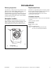
Introduction Delivery Inspection Replacement Parts Upon delivery, visually inspect crate, protective cover and unit for any visible shipping damage. If the crate, protective cover or unit is damaged or signs of possible damage are evident, have the carrier note the condition on the shipping papers before the shipping receipt is signed or advise the carrier of the condition as soon as it is discovered.
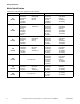
Specifications and Dimensions High Speed Models Models Specifications 40H 60H 80H 100H 125H 140H 175H Overall Width, in. (mm) 32 (813) 34.5 (876) 42.5 (1080) 42.5 (1080) 50.3 (1278) 50.3 (1278) 50.3 (1278) Overall Height, in. (mm) 57 (1448) 62.6 (1590) 70 (1778) 70 (1778) 77.1 (1958) 77.1 (1958) 77.1 (1958) Overall Depth, in. (mm) 45.6 (1158) 47.8 (1214) 51.4 (1306) 56.4 (1433) 56.1 (1425) 59.1 (1501) 64.
Specifications and Dimensions Table 1 (continued) Models Specifications 40H 60H 80H 100H 125H 140H 175H Number of Dry Chemical Compartments, (std/opt) 1/5 1/5 1/5 1/5 1/5 1/5 1/5 Number of Liquid Supply Connections, (std/opt) 6/12 6/12 6/12 6/12 6/12 6/12 6/12 Chemical Supply System Cylinder Speeds/Centrifugal Force Data 10-60 (0.05-1.4) 10-60 (0.04-1.6) 10-60 (0.05-1.9) 10-60 (0.05-1.9) 10-55 (0.06-1.9) 10-55 (0.06-1.9) 10-55 (0.06-1.
Specifications and Dimensions Medium Speed Models Models Specifications 40M 60M 80M 100M 140M Overall Width, in. (mm) 32 (813) 34.5 (876) 42.5 (1080) 42.5 (1080) 50.3 (1278) Overall Height, in. (mm) 57 (1448) 62.6 (1590) 70 (1778) 70 (1778) 77.1 (1958) Overall Depth, in. (mm) 45.6 (1158) 47.8 (1214) 51.4 (1306) 56.4 (1433) 59.1 (1501) Overall Dimensions Weight and Shipping Information Net Weight, lbs.
Specifications and Dimensions Table 2 (continued) Models Specifications 40M 60M 80M 100M 140M Number of Dry Chemical compartments, (std/opt) 1/5 1/5 1/5 1/5 1/5 Number of Liquid Supply Connections, (std/opt) 6/12 6/12 6/12 6/12 6/12 Liquid Supply Connection Size 1/2 NPT 1/2 NPT 1/2 NPT 1/2 NPT 1/2 NPT 1 1 1 1 1 3 (2.3) 3 (2.3) 5 (3.7) 5 (3.7) 7.5 (5.6) 10-60 (0.05-1.4) 10-60 (0.04-1.6) 10-60 (0.05-1.9) 10-60 (0.05-1.9) 10-55 (0.06-1.
Specifications and Dimensions Machine Dimensions Dimensional Clearances Allow 24 inches (600 mm) at the rear of the machine and 18 inches (450 mm) is recommended at the sides for maintenance, inspection and adjustment. In multiple installations, allow 18 inches (450 mm) between machines. Machine dimensions are indicated in Figure 2 through Figure 8. For minimum clearances, refer to Figure 9.
Specifications and Dimensions 40 Pound Models L 4 K 3 1 A 5 J 2 6 7 E F C O G N H M D I B 10 P 8 9 REAR FRONT TOP PHM727N PHM727N 1 2 3 4 5 External Supply Connection Auxiliary Hot Water Cold Water Greasing Points 6 7 8 9 10 External Supply Wiring Connection Power Inlet Steam Inlet Auxiliary Drain Drain Figure 2 A 45.6 in. (1158 mm) I 11.7 in. (297 mm) B 32 in. (813 mm) J 10.25 in. (260 mm) C 25.5 in. (648 mm) K 19.35 in. (491 mm) D 22.5 in. (572 mm) L 27.93 in.
Specifications and Dimensions 60 Pound Models M 4 L 3 1 K 2 5 6 7 10 A E C F G H N O I D J B P 9 8 TOP PHM728N REAR FRONT PHM728N 1 2 3 4 5 External Supply Connection Auxiliary Hot Water Cold Water Greasing Points 6 7 8 9 10 External Supply Wiring Connection Power Inlet Auxiliary Drain Drain Steam Inlet Figure 3 A 47.8 in. (1214 mm) I 38.5 in. (978 mm) B 34.5 in. (876 mm) J 11.7 in. (297 mm) C 28.8 in. (732 mm) K 11.5 in. (292 mm) D 25.8 in. (655 mm) L 21.1 in.
Specifications and Dimensions 80 Pound Models O 1 4 3 2 N 5 M 6 7 10 A F G E C H I P J Q K D L B S R 9 8 TOP PHM729N REAR FRONT PHM729N 1 2 3 4 5 External Supply Connection Auxiliary Hot Water Cold Water Greasing Points 6 7 8 9 10 External Supply Wiring Connection Power Inlet Auxiliary Drain 3 in. (76.2 mm) Drain Steam Inlet Figure 4 A 51.4 in. (1306 mm) K 38.4 in. (975 mm) B 42.5 in. (1080 mm) L 11.7 in. (297 mm) C 29.6 in. (752 mm) M 12.25 in. (311 mm) D 26.6 in.
Specifications and Dimensions 100 Pound Models O 1 4 3 2 N 5 M 6 7 10 A F G H E C I P J Q I K D L B 9 S TOP R 8 REAR FRONT PHM730N PHM730N 1 2 3 4 5 External Supply Connection Auxiliary Hot Water Cold Water Greasing Points 6 7 8 9 10 External Supply Wiring Connection Power Inlet Auxiliary Drain 3 in. (76.2 mm) Drain Steam Inlet Figure 5 A 56.4 in. (1433 mm) K 38.4 in. (975 mm) B 42.5 in. (1080 mm) L 11.7 in. (297 mm) C 30.12 in. (765 mm) M 12.25 in. (311 mm) D 27.
Specifications and Dimensions 125 Pound Models 3 N 4 O P Q 5 2 6 1 9 A F G H E C I J R K S L D M B T U TOP 8 REAR FRONT 7 PHM731N 1 2 3 4 5 External Supply Connection Hot Water Cold Water Auxiliary External Supply Wiring Connection 6 7 8 9 Power Inlet 3 in. (76.2 mm) Drain Auxiliary Drain Steam Inlet Figure 6 A 56.1 in. (1425 mm) L 45.3 in. (1151 mm) B 50.3 in. (1278 mm) M 11.6 in. (295 mm) C 34.3 in. (871 mm) N 6.7 in. (170 mm) D 31.3 in. (795 mm) O 18.
Specifications and Dimensions 140 Pound Models P O N 3 2 M L 4 5 1 A F E G 6 R H I 10 C D Q 7 J K B T TOP 9 FRONT S 8 REAR PHM732N PHM732N 1 2 3 4 5 External Supply Connection Cold Water Hot Water Auxiliary External Supply Wiring Connection 6 7 8 9 10 Power Inlet Greasing Points Auxiliary Drain 3 in. (76.2 mm) Drain Steam Inlet Figure 7 A 59.1 in. (1501 mm) K 11.7 in. (297 mm) B 50.3 in. (1278 mm) L 12 in. (305 mm) C 34.3 in. (871 mm) M 15.18 in. (386 mm) D 31.3 in.
Specifications and Dimensions 175 Pound Models P O N 3 2 M L 4 5 1 A F E C G H 6 R 10 Q I 7 J D K B T TOP 9 FRONT S 8 REAR PHM733N 1 2 3 4 5 External Supply Connection Cold Water Hot Water Auxiliary External Supply Wiring Connection 6 7 8 9 10 Power Inlet Greasing Points Auxiliary Drain 3 in. (76.2 mm) Drain Steam Inlet Figure 8 A 64.1 in. (1628 mm) K 11.6 in. (295 mm) B 50.3 in. (1278 mm) L 15.6 in. (396 mm) C 34.3 in. (871 mm) M 21.6 in. (549 mm) D 31.3 in.
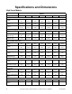
Specifications and Dimensions Machine Size Basket Diameter Net Wt. of Machine (lbs.) Height of Basket Center (in.) Max RPM G Calculated Static Load (lbs.) Static Floor Pressure (lbs./ft2) Dynamic Load (lbs.) Max Vertical Load (lbs.) Max Dynamic Floor Pressure (lbs./ft2) Base Moment (lbs./ft.) Load Freq (Hz) Floor Load Data 40M 100G 27 1583 33.35 511 100 1701 179 786 2440 256.8 2185 8.52 40M 150G 27 1583 33.35 625 149.6 1701 179 706 2359 248.3 1961 10.
Specifications and Dimensions Installation Instructions Mounting Bolt Installation Requirements Surface These machines must be securely anchored on a solid, flat reinforced concrete surface capable of withstanding the weight of the machine and the considerable forces generated during the spin/extract cycle. Surface should be a high quality concrete (minimum 3500 psi test strength) and at least 12 in. (305 mm) thickness for all models. The surface should be clean, flat and free of irregularities.
Specifications and Dimensions Clearances IMPORTANT: If the machines are to be mounted less than 18 in. (457 mm) from each other or less than 18 in. (457 mm) from a side wall, only the inside bolt holes will be accessible. If the machines are to be mounted less than 6 in. (152 mm) from each other, a wall or other equipment, they must be installed without using the skirt around the bottom, as it cannot be reinstalled after the machines are in place. 18 in. (recommended) (457 mm) 1* in.
Specifications and Dimensions Mounting Bolt Hole Locations Grouting and Setting Machine Use a sturdy template to guide hammer-drill into floor. A heavy steel template/drill guide is available from your distributor. Make sure to follow bolt manufacturer’s recommendation for bit size for the particular anchors you are using. The dimensions shown in Figures 11 through 13 are patterns for various models. Installing Anchors 1. Measure holes to verify that they match bolt hole pattern in base of frame. 2.
Specifications and Dimensions Mounting Bolt Hole Locations IMPORTANT: All drawings are not to scale. 40 Pound Models WALL 24 in. (610 mm) min.
Specifications and Dimensions Model A 40 Pound 4 in. (102 mm) B 1 in. (25 mm) C 5.5 in. (140 mm) D 30.5 in. (775 mm) E 17.5 in. (445 mm) F 9 in. (229 mm) G 5.5 in. (140 mm) H 31.32 in. (796 mm) I 22.85 in. (580 mm) J 34.73 in. (882 mm) K 27.34 in. (694 mm) L 37.03 in. (941 mm) M 42.78 in. (1087 mm) N 21 in. (533 mm) O 30 in. (762 mm) P 32 in.
Specifications and Dimensions 60, 80 and 100 Pound Models WALL 24 in. (610 mm) min.
Specifications and Dimensions Model 60 Pound 80 Pound 100 Pound A 4 in. (102 mm) 1.5 in. (38 mm) 6.5 in. (165 mm) B 1.5 in. (38 mm) 1.5 in. (38 mm) 1.5 in. (38 mm) C 5.5 in. (140 mm) 7 in. (178 mm) 7 in. (178 mm) D 35 in. (889 mm) 41.5 in. (1054 mm) 41.5 in. (1054 mm) E 26.25 in. (667 mm) 33 in. (838 mm) 33 in. (838 mm) F 17.5 in. (445 mm) 22 in. (559 mm) 22 in. (559 mm) G 8.75 in. (222 mm) 11 in. (279 mm) 11 in. (279 mm) H 4 in. (102 mm) 4 in. (102 mm) 4 in.
Specifications and Dimensions 125, 140 and 175 Pound Models WALL 24 in. (610 mm) min.
Specifications and Dimensions Model 125 Pound 140 Pound 175 Pound H-Series H-Series H-Series A 3.93 in. (100 mm) 3.5 in. (89 mm) 2.5 in. (64 mm) B 1.5 in. (38 mm) 1.5 in. (38 mm) 1.5 in. (38 mm) C 7 in. (178 mm) 7 in. (178 mm) 7 in. (178 mm) D 47.5 in. (1207 mm) 49 in. (1245 mm) 54 in. (1372 mm) E 27 in. (686 mm) 27 in. (686 mm) 27 in. (686 mm) F 18 in. (457 mm) 18 in. (457 mm) 18 in. (457 mm) G 9 in. (229 mm) 9 in. (229 mm) 9 in. (229 mm) H 3.5 in. (89 mm) 3.5 in.
Specifications and Dimensions Water Connection 1 WARNING To prevent personal injury, avoid contact with inlet water temperatures higher than 125° Fahrenheit (51° Celsius) and hot surfaces. W748 Water service should have the following: 2 • Hot water temperature should be a maximum of 190°F (88°C). • Water pressure should be between 30 and 85 psi (2 to 7 bar). • Install screen filters in water supply lines to keep rust, grit or other foreign material out of solenoid valves.
Specifications and Dimensions Drain Connection Requirements If proper drain size is not available or practical, a surge tank is required. A surge tank along with a sump pump should be used when gravity drainage is not possible. A flexible connection must be made to a vented drain system to prevent an air lock and to prevent siphoning. Increasing drain hose length, installing elbows or causing bends will decrease drain flow rate and increase drain times, impairing machine performance.
Specifications and Dimensions 1 2 3 4 5 6 7 PHM621N 1 2 3 4 5 6 7 Rear of Machine Drain Pipe 1 in. (25.4 mm) Minimum Air Gap Steel Grate Drain Trough Strainer Waste Line Figure 15 NOTE: Installation of additional machine will require proportionately larger drain connections.
Specifications and Dimensions Electrical Installation Requirements IMPORTANT: Electrical ratings are subject to change. Refer to serial decal for electrical ratings information specific to your machine. WARNING This machine must be installed, adjusted, and serviced by qualified electrical maintenance personnel familiar with the construction and operation of this type of machinery. They must also be familiar with the potential hazards involved.
Specifications and Dimensions The AC drive provides thermal overload protection for the drive motor. However, a separate circuit breaker or electrical supply disconnecting device must be installed for complete electrical overload protection. This prevents damage to the AC drive by disconnecting all legs if one should be lost accidentally. IMPORTANT: Do NOT use fuses in place of a circuit breaker. CAUTION Do not use a phase adder on any variablespeed machine.
Specifications and Dimensions Pocket Hardmount Electrical Specifications mm2 140M AWG 100M Breaker 80M Full Load Amps 60M mm2 40M AWG 175H Breaker 140H Full Load Amps 125H Wire 100H Phase 80H Cycle 60H Electric Heat Voltage 40H Standard Code Model Voltage Designation N 380 – 480 50/60 3 3 4 15 14 2.5 29 35 8 10 Q 200 – 240 50/60 3 3 8 15 14 2.5 56 60 6 16 X 200 – 240 50/60 1/3 2/3 11 15 14 2.
Specifications and Dimensions Making Connections to Machine After electrical service feeder has been installed and electrical service voltage verified by a volt meter, follow this procedure to connect service to the equipment. 1. Remove screw securing electrical service connection panel and remove panel from machine. 7. Power up machine temporarily and, using a volt meter, verify the voltage on transformer secondary is between 100 and 130 VAC.
Specifications and Dimensions Steam Requirements (Steam Heat Option Only) For machines equipped with optional steam heat, install piping in accordance with approved commercial steam practices. Steam requirements are shown in Table 16. WARNING NOTE: Failure to install supplied steam filter may void warranty. Hot Surfaces. Will cause severe burns. Turn steam off and allow steam pipes, connections and components to cool before touching.
Specifications and Dimensions Chemical Injection Supply System WARNING Dangerous Chemicals. May damage eyes and skin. Wear eye and hand protection when handling chemicals; always avoid direct contact with raw chemicals. Read the manufacturer’s directions for accidental contact before handling chemicals. Ensure an eye-rinse facility and an emergency shower are within easy reach. Check at regular intervals for chemical leaks. W363 IMPORTANT: Undiluted chemical dripping can damage the machine.
Specifications and Dimensions HOLD HOLD PUMP SYSTEM INTERFACE MODULE WARNING HOLD RELAY COM HOLD RELAY NO COM This machine is not designed to provide power for a chemical pump system! Connecting such a load to the machine’s controls may overload the control transformer! Never connect power for any device to the machine’s main power terminal block – this is a violation of the NEC and other electrical regulations.
First Start-Up IMPORTANT: The following safety checks are to be performed BEFORE initial start-up. 1. Make sure all electrical and plumbing connections have been made in accordance with applicable codes and regulations. 2. Make sure machine is electrically grounded. This is a high leakage current device! Improper grounding can cause electrical shock hazards and EMI problems. 3. Make sure all service connections (water, drain, electrical, steam, etc.
Operation General Operation Instructions 4. Enter number of desired program. 1. Open door. 2. Load to capacity. DO NOT OVERLOAD. RUN WARNING PROG Be careful around the open door, particularly when loading from a level below the door. Impact with door edges can cause personal injury. 1 2 3 4 5 6 7 8 9 PS40 0 SW025 PHM1398C PHM1398C Figure 22 5. Fill dispenser cups with appropriate chemicals, if necessary. PHM833N Figure 20 3. Close and lock door. PHM840N Figure 23 6.
Operation 7. Machine door will automatically lock and cycle will begin. 8. When program is completed, display will display “open door” and door will automatically unlock and is ready to be opened. WARNING The PS40’s fault codes indicate potentially hazardous operating conditions. If a Fault occurs the machine should be shut off and locked out until a service technician can repair the machine. All fault codes are indicated by a flashing “Fn” display.
Maintenance Maintenance procedures described below will prolong life of machine and help prevent accidents. 3. Inspect steam hose connections for leaks (where applicable). WARNING WARNING Sharp edges can cause personal injury. Wear safety glasses and gloves, use proper tools and provide lighting when handling sheet metal parts. To reduce the risk of electrical shock, serious injuryordeath,disconnecttheelectricalpowerto washer-extractor before examining the wiring.
Maintenance Weekly The grease must have the following characteristics: 1. Check machine for leaks. a. Start an unloaded cycle to fill machine. • NLGI Grade 2 (Recommended: Shell Alvania® #71125) b. Verify that door and door gasket do not leak. • Lithium-based c. Verify that drain valve is operating and that drain system is free from obstruction. If water does not leak out during prewash segment, drain valve is closed and functioning properly.
Maintenance 3. Verify V-belts are properly aligned by checking pulley alignment. Place a straight edge across both pulley faces. The straight edge should make contact with pulleys in two places. Refer to Figure 25. Quarterly NOTE: Disconnect power to washer-extractor before performing quarterly maintenance procedures. 1. Tighten door hinges and fasteners, if necessary. 1 2 2. Tighten anchor bolts, if necessary. 5 3 3. Verify that drain motor shield is in place and secure. 4.
Maintenance Care of Stainless Steel • Remove dirt and grease with detergent and water. Thoroughly rinse and dry after washing. • Avoid contact with dissimilar metals to prevent galvanic corrosion when salty or acidic solutions are present. • Do not allow salty or acidic solutions to evaporate and dry on stainless steel. Wipe clean of any residues. • Rub in direction of polish lines or “grain” of stainless steel to avoid scratch marks when using abrasive cleaners.
Disposal of Unit This appliance is marked according to the European directive 2002/96/EC on Waste Electrical and Electronic Equipment (WEEE). This symbol on the product or on its packaging indicates that this product shall not be treated as household waste. Refer to Figure 26. Instead it shall be handed over to the applicable collection point for the recycling of electrical and electronic equipment.