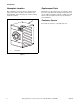
Operation/Maintenance Washer-Extractors Cabinet Freestanding Refer to Page 3 for Model Identification H CFD11C Para bajar una copia de estas instrucciones en español, visite www.comlaundry.com. Keep These Instructions for Future Reference. (If this machine changes ownership, this manual must accompany machine.) Part No. 9001910R1 www.comlaundry.
Table of Contents Introduction......................................................................................... Model Identification ............................................................................. Nameplate Location.............................................................................. Replacement Parts ................................................................................ Customer Service................................................................................
Notes 2 © Copyright, Alliance Laundry Systems LLC – DO NOT COPY or TRANSMIT 9001910
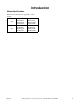
Introduction Model Identification Information in this manual is applicable to these models: 9001910 18 NX18BVPA6 NX18BVPA7 NX18BVQA6 NX18BVQA7 NX18BVXA6 NX18BVXA7 NX18BVXM6 NX18BVXM7 30 NX30BVPA6 NX30BVPA7 NX30BVQA6 NX30BVQA7 NX30BVXA6 NX30BVXA7 NX30BVXM6 NX30BVXM7 © Copyright, Alliance Laundry Systems LLC – DO NOT COPY or TRANSMIT 3
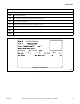
Introduction Nameplate Location Replacement Parts The nameplate is located at the rear of the machine. Always provide the machine’s serial number and model number when ordering parts or when seeking technical assistance. If literature or replacement parts are required, contact the source from which the machine was purchased or contact Alliance Laundry Systems at (920) 748-3950 for the name and address of the nearest authorized parts distributor.
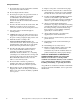
Introduction Model Number Familiarization Guide Sample Model Number: NX18BVXM60001 NX Model Number Prefix 18 Washer-Extractor Capacity (pounds dry weight of laundry) B Type of Electrical Control V Washer-Extractor Speed Capability (V = Variable-Speed) X Voltage Code M6 0001 Design Series (M=Domestic, A=International) Option Identification (varies from machine to machine) NX18BVXM60001 6 50 60 18 15 2/3+PE 8 1 1000 EXAMPLE OF NAMEPLATE CFD22N CFD22N Figure 2 9001910 © Copyright, Alliance
Notes 6 © Copyright, Alliance Laundry Systems LLC – DO NOT COPY or TRANSMIT 9001910
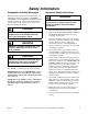
Safety Information Explanation of Safety Messages Throughout this manual and on machine decals, you will find precautionary statements (“DANGER,” “WARNING,” and “CAUTION”) followed by specific instructions. These precautions are intended for the personal safety of the operator, user, servicer, and those maintaining the machine. DANGER Indicates an imminently hazardous situation that, if not avoided, will cause severe personal injury or death.
Safety Information 9. Do not install or store the washer where it will be exposed to water and/or weather. 10. Do not tamper with the controls. 11. Do not repair or replace any part of the washer, or attempt any servicing unless specifically recommended in the user-maintenance instructions or in published user-repair instructions that the user understands and has the skills to carry out. 12.
Preliminary Information About the Control Power Failure Recovery WE-8 B-control on the washer-extractor is an advanced, programmable computer that allows the owner to create wash programs. If a cycle in process and the power fails, the user has one minute to press START (enter) to continue the cycle. If START (enter) is not pressed within the minute, program will drain water and basket will not rotate (safe mode). Control will test speed sensor by steering the wash speed for a brief time.
Notes 10 © Copyright, Alliance Laundry Systems LLC – DO NOT COPY or TRANSMIT 9001910
Operation Control Panel 12 2 12 1 2 1 5 WASH ADD BLEACH RINSE SPIN NORMAL PERM PRESS HOT WARM NORMAL PERM PRESS WARM COLD QUICK WASH QUICK WASH 6 95C 95C 6 7 60C 60C 7 40C 40C START DOOR HOT COLD 10 30C 9 9 11 4 3 10CHM488R INTERNATIONAL MODELS CHM482R CHM482R 1 2 3 4 5 6 8 < HOT < DELICATE 11 3 4 DOMESTIC MODELS 8 WARM HEAVY SOIL 5 Cycle 1 Cycle 2 Cycle 3 Cycle 4 Cycle 5 Cycle 6 CHM488R 7 8 9 10 11 12 Cycle 7 Cycle 8 Down Edit/Change keypad Up Edit/Chang
Operation Operating Instructions 1. Turn on main power source (circuit breaker). 4. Close door by pushing door handle towards machine. Refer to Figure 6. 2. Push black button and pull door handle away from machine to open door. Refer to Figure 4. CFD54N CFD54N Figure 6 CFD52N CFD52N Figure 4 3. Load to capacity whenever possible. DO NOT OVERLOAD. Refer to Figure 5. 5. The default wash cycle will display. NOTE: Perm Press Cold is the default cycle for coin models if none is selected.
Operation 6. If desired, select a different cycle at this point or after satisfying vend. The LED indicator for that cycle will light. 8. Add coins to machine. As each coin is added, the vend counts down to the amount remaining. Refer to Figure 8. 7. Add liquid and/or powder supplies to supply dispenser. Refer to Figure 8. 9. When applicable, add bleach to compartment 2 when the ADD BLEACH LED is lit. a. Add detergent to compartment 1. 10. Press the desired wash cycle keypad. b.
Notes 14 © Copyright, Alliance Laundry Systems LLC – DO NOT COPY or TRANSMIT 9001910
Maintenance Routine maintenance maximizes operating efficiency and minimizes downtime. The maintenance procedures described below will prolong the life of the machine and help prevent accidents. CAUTION End of day 1. Clean the fan of the AC drive box. 2. Clean the entire cabinet of the machine regularly and remove all traces of soap, etc. 3. Remove all detergent residue in the soap dispenser with hot water. Replace all panels that are removed to perform service and maintenance procedures.
Maintenance Monthly 5. Remove back panel and check overflow hose and drain hose for leaks. NOTE: Disconnect power to the machine at its source before performing the monthly maintenance procedures. 6. Clean inlet hose filter screen: 1. Clean the AC drive Box. a. Turn water off and allow valve to cool, if necessary. b. Unscrew inlet hose and remove filter screen. a. Remove the AC drive box cover. b. Blow the fins clean using compressed air at a pressure of 60-90 psi or by using canned compressed air.
Maintenance Daily Preventive Maintenance Checklist Machine ____________________________ Operator Week of: ________________ Days ___________________________ Checks 1 2 3 4 5 6 7 Beginning of Day 1. Inspect water inlet valve hose connections on the back of the machine for leaks. 2. Inspect steam hose connections for leaks, where applicable. 3. Verify that insulation is intact on all external wires and that all connections are secure. 4. Inspect door lock and interlock before starting operation: a.
Maintenance Weekly Preventive Maintenance Checklist Machine ____________________________ Operator Month __________ Week Ending: ___________________________ Checks / / / / / 1. Check the machine for leaks: a. Start an unloaded cycle to fill the machine. b. Verify that door and door gasket do not leak. c. Verify that the drain valve is operating. 2. 3. 4. 5. 6. 7.
Maintenance Monthly Preventive Maintenance Checklist Machine ____________________________ Operator Month ___________________________ Checks Observe All Safety Warnings! Disconnect power to the machine before performing the monthly maintenance procedures. 1. Clean the AC drive box. 2. Belts a. Check belts for uneven wear and frayed edges. b. Verify that belts are properly aligned by checking pulley alignment. 3. Remove back panel and check overflow hose and drain hose for leaks. 4.
Maintenance Yearly Preventive Maintenance Checklist Machine ____________________________ Operator Year ___________________________ Checks Observe All Safety Warnings! Disconnect power to the machine before performing the quarterly maintenance procedures. 1. Check if the machine is working properly. If you see or hear any abnormal function on the machine call a service technician. 2. 3. 4. 5. 6. 7. 8. 9.