Cabinet Freestanding Refer to Page 2 for Model Identification CFD15C CFD15C 33, 40, 55 and 75 Models CFD19C CFD19C 18, 25, 30 and 35 Models CFD20C 100, 135, 165 and 200 Models CFD20C Keep These Instructions for Future Reference. (If this machine changes ownership, this manual must accompany machine.) Part No. 9001001R7 www.comlaundry.
Table of Contents Introduction......................................................................................... Model Identification ............................................................................. Nameplate Location.............................................................................. Replacement Parts ................................................................................ Customer Service................................................................................
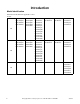
Introduction Model Identification Information in this manual is applicable to these models: HX18PVQM6 HX18PVQM7 HX18PVXM6 HX18PVXM7 SX18PVPA7 SX18PVQM6 SX18PVQM7 SX18PVXM6 SX18PVXM7 HX25PVQM6 HX25PVQM7 HX25PVXM6 HX25PVXM7 SX25PVQM6 SX25PVQM7 SX25PVXM6 SX25PVXM7 18 25 UX18PVNA6 UX18PVNA7 UX18PVPA6 UX18PVPA7 UX18PVQA6 UX18PVQA7 UX18PVQM6 UX18PVQM7 UX18PVXA6 UX18PVXA7 UX18PVXM6 UX18PVXM7 UX25PVNA6 UX25PVNA7 UX25PVPA6 UX25PVPA7 UX25PVQA6 UX25PVQA7 UX25PVQM6 UX25PVQM7 UX25PVXA6 UX25PVXA7 UX25PVXM6 UX25PVXM
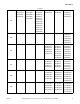
Introduction HX35PVQM6 HX35PVQM7 HX35PVXM6 HX35PVXM7 35 SX35PVQM6 SX35PVQM7 SX35PVXM6 SX35PVXM7 SX35PVNM7 continued UX35PVNA6 UX35PVNA7 UX35PVPA6 UX35PVPA7 UX35PVQA6 UX35PVQA7 UX35PVQM6 UX35PVQM7 UX35PVXA6 UX35PVXA7 UX35PVXM6 UX35PVXM7 HX35PVQU6 HX35PVXU6 SX35PVQU6 SX35PVXU6 40 HX55PVNU6 HX55PVNU7 HX55PVQU6 HX55PVQU7 HX55PVXU6 HX55PVXU7 55 75 100 135 HX75PVNU6 HX75PVNU7 HX75PVPU7 HX75PVQU6 HX75PVQU7 SX55PVNU6 SX55PVNU7 SX55PVPU6 SX55PVPU7 SX55PVQU6 SX55PVQU7 SX55PVXU6 SX55PVXU7 SX75PVNU6 SX75P
Introduction continued 165 200 4 HX165PVNU6 HX165PVNU7 HX165PVPU7 HX165PVQU6 HX165PVQU7 SX165PVNU6 SX165PVNU7 SX165PVPU7 SX165PVQU6 SX165PVQU7 HX200PVNU7 HX200PVPU7 HX200PVQU7 SX200PVNU7 SX200PVPU7 SX200PVQU7 © Copyright, Alliance Laundry Systems LLC – DO NOT COPY or TRANSMIT UX165PVNU6 UX165PVNU7 UX165PVPU6 UX165PVPU7 UX165PVQU6 UX165PVQU7 UX200PVNU7 UX200PVPU7 UX200PVQU7 9001001
Introduction Nameplate Location The nameplate is located at the rear of the machine. Always provide the machine’s serial number andmodel number when ordering parts or when seeking technical assistance.
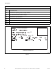
Introduction Model Number Familiarization Guide Sample Model Number: *X55PVXM60001 *X Model Number Prefix 55 Washer-Extractor Capacity (pounds dry weight of laundry) P Type of Electrical Control (P = WE-6 Computer) V Washer-Extractor Speed Capabilities X Electrical Characteristics M6 0001 Design Series Option Identification (varies from machine to machine) * Denotes Brand * X55PVXM60001 12 50 60 55 15 2/3+PE 25 1/3 1000 EXAMPLE OF NAMEPLATE CFD29N CFD29N Figure 1 6 © Copyright, Allianc
Safety Information Explanation of Safety Messages Precautionary statements (“DANGER,” “WARNING,” and “CAUTION”), followed by specific instructions, are found in this manual and on machine decals. These precautions are intended for the personal safety of the operator, user, servicer, and those maintaining the machine.
Safety Information 9. Do not install or store the washer where it will be exposed to water and/or weather. 10. Do not tamper with the controls. 11. Do not repair or replace any part of the washer, or attempt any servicing unless specifically recommended in the user-maintenance instructions or in published user-repair instructions that the user understands and has the skills to carry out. 12.
Safety Information WARNING CAUTION This machine must be installed, adjusted, and serviced by qualified electrical maintenance personnel familiar with the construction and operation of this type of machinery. They must also be familiar with the potential hazards involved. Failure to observe this warning may result in personal injury and/or equipment damage, and may void the warranty. SW004 IMPORTANT: Ensure that the recommended clearances for inspection and maintenance are provided.
Safety Information Operator Safety Do not bypass any safety devices in the machine. WARNING WARNING NEVER insert hands or objects into basket until it has completely stopped. Doing so could result in serious injury. SW012 To ensure the safety of machine operators, the following maintenance checks must be performed daily: Never operate the machine with a bypassed or disconnected balance system.
Preliminary Information About the Control Power Failure Recovery WE-8 computer on the washer-extractor is an advanced, programmable computer that allows the owner to create wash programs. If a cycle is in process and the power fails, cycle status is saved in memory without power being applied. The control is factory set-up with 42 pre-programmed cycles and is ready for operation. Refer to Pre-Programmed Cycles section in the Programming manual.
Preliminary Information Control Identification 3 2 5 1 4 M172 1 2 3 Keypad Display Emergency Stop Button 4 5 Key Switch Serial Port Figure 2 12 © Copyright, Alliance Laundry Systems LLC – DO NOT COPY or TRANSMIT 9001001
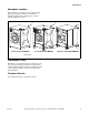
Operation Load the Machine For 100 - 200 models: 1. Push on the doorlock system to open the door. For 18 - 75 models: 1. Pull the door handle towards you to open the door. Some models may have a door handle with a button that must be pressed. 2. Load the drum to the specified capacity. 3. Close the door by pushing the door handle towards the machine. 2. Load the drum to the specified capacity. 3. Close the door by pushing the door handle towards the machine.
Operation Start a Program Cycle 00 After powering up the control, “Cycle 00” will show on the display. Press the desired program number (example: program 23). Cycle 23 The display will show the cycle (example: “Cycle 23”). Press “Start” to run the program. If the program does not exist, the display will show “No Cycle 23”. See program mode to create a program. No Cycle 23 Please close door If the door is not closed, the display will show “Please close door”.
Operation Special Options in Run Mode S01 C23 0:04:59 80°F High While the machine is running press the “Display Temp” button. Level : 2.5 cm 62°F 40rpm L Level: 2.5 cm: Water level in the bath. If the machine is filling with water this value will increase. If in a drain step this value will decrease. 62°F: The water temperature. 40rpm: The measured rpm of the drum. L: Rotation direction of the drum L (left), R (right) Press the “Display Temp” button to go back.
Operation Stop the Machine S01 C23 0:04:00 Spin 1 Press the “Stop” button. Waterlevel 10.2 cm If there is water in the machine the display will show “Waterlevel xx.x cm” while the machine is draining the water. Coast down If the machine is spinning the display will show “Coast down”. Please open door When the water is out and the drum has stopped moving the display will flash between “Please open door” and “Done cycle 23” until the door is open.
Operation Error Messages Door Error Door error If the door is closed after start the control will try to lock the door. If the door will not lock “Door error” will display. Possible Faults: Wiring is not connected properly. Coil to lock the door has failed. Mechanical problem on the door lock. Fill Alarm Didn’t fill within time If machine does not reach programmed water level within time programmed for step, a fill alarm occurs.
Operation Fill Alarm (Continued) Possible Faults: Wiring is not connected properly to the inlet valves. The inlet valve is broken. There is a problem with the water supply. The inlet valves are blocked by dirt. The water pressure hose is broken or not connected properly. Didn’t drain within time Drain Alarm If drain step is NOT followed by a spin and if machine does not empty within the time programmed for drain step, a drain alarm occurs. Display will read “Didn’t drain within time.
Operation If there was a problem during heating in a step at the end of the program, the control will show “Temperature sensor error”. The temperature was never reached in this cycle. Temperature sensor error Possible Faults: Bad temperature probe. Wiring to electrical or steam heating relay has failed. Electrical heating elements or steam valve is broken. NOTE: If the cycle aborted, it may be due to a temperature sensor error.
Maintenance Routine maintenance maximizes operating efficiency and minimizes downtime. The maintenance procedures described below will prolong the life of the machine and help prevent accidents. CAUTION Replace all panels that are removed to perform service and maintenance procedures. Do not operate the machine with missing guards or with broken or missing parts. Do not bypass any safety devices. SW019 Daily, weekly, monthly, and yearly checklists are provided at the end of this section.
Maintenance Weekly End of day 1. Clean the fan of the AC drive box. 2. Clean the entire cabinet of the machine regularly and remove all traces of soap, etc. 3. Remove all detergent residue in the soap dispenser with hot water. 4. Clean the door gasket and remove all detergents and other products. 5. Shut off the main water, steam and power connections at the end of each day. Do not change the setting of the water inlet taps on boiler fed machines once these have been installed. 6.
Maintenance 3. Remove back panel and check overflow hose and drain hose for leaks. 4. Clean inlet hose filter screen: a. Turn water off and allow valve to cool, if necessary. b. Unscrew inlet hose and remove filter screen. c. Clean with soapy water, rinse and reinstall. Replace if worn or damaged. Yearly 1. Replace the automatic lubricator (only for 75-200 machine). Failure to do so could void the warranty. 2. Check if the machine is working properly.
Maintenance Daily Preventive Maintenance Checklist Machine ____________________________ Operator Week of: ________________ Days ___________________________ Checks 1 2 3 4 5 6 7 Beginning of Day 1. Inspect water inlet valve hose connections on the back of the machine for leaks. 2. Inspect steam hose connections for leaks, where applicable. 3. Inspect door lock and interlock before starting operation: a. Attempt to start the machine with door open. b. Close the door and start the machine.
Maintenance Weekly Preventive Maintenance Checklist Machine ____________________________ Operator Month __________ Week Ending: ___________________________ Checks / / / / / 1. Check the machine for leaks: a. Start an unloaded cycle to fill the machine. b. Verify that door and door gasket do not leak. c. Verify that the drain valve is operating. 2. 3. 4. 5. 6. 7.
Maintenance Monthly Preventive Maintenance Checklist Machine ____________________________ Operator Month ___________________________ Checks Observe All Safety Warnings! Disconnect power to the machine before performing the monthly maintenance procedures. 1. Clean the AC drive box. 2. V-belts a. Check V-belts for uneven wear and frayed edges. b. Verify that V-belts are properly aligned by checking pulley alignment. 3. Remove back panel and check overflow hose and drain hose for leaks. 4.
Maintenance Yearly Preventive Maintenance Checklist Machine ____________________________ Operator Year ___________________________ Checks Observe All Safety Warnings! Disconnect power to the machine before performing the quarterly maintenance procedures. 1. Replace the automatic lubricator (only for 75-200 machines). 2. Check if the machine is working properly. If you see or hear any abnormal function on the machine call a service technician. 3. 4. 5. 6. 7. 8. 9.