
Specifications


© Copyright, Alliance Laundry Systems LLC – DO NOT COPY or TRANSMIT
Installation
F8429301ENR9
66
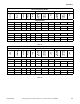
Connection of External Liquid Supplies
20 – 100 Pound OPL Models
1. Facing the rear of the machine, locate the five
3/8 inch supply hose connections found on the
right-hand side of the valve panel. Refer to
Figure 53.
Figure 53
2. Drill through the five plastic holes on the valve
panel for the external supply hoses as needed.
3. Remove plastic debris.
4. Attach the external supply hoses to the ports at
each of the drilled holes.
5. Secure with proper clamps.
NOTE: Do not attempt to make chemical injection
supply pump electrical connections to points other
than those provided specifically for that purpose by
the factory.
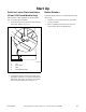
125 Pound OPL Models
(With Optional Dispenser)
Refer to Figure 54.
1. Remove plugs from base. Plugs are assembled
inside tubing ring.
2. Install strain reliefs with the seal nuts.
3. Insert tubes through base. Do not remove dry
supply cups. Tube should extend into plastic cup,
with exception of softener tube, which should be
routed to outside of cup.
4. Tighten seal nut to prevent tubing from escaping
assembly.
Figure 54
CHM2388N
1 External Supply Hose Opening
CHM2388N
20-100 POUND MODELS
VALVE PANEL – REAR VIEW
1
CHM2001N
1 Strain Relief for Liquid Chemical Supply
Lines
2 Supply Dispenser Lid
3 Four Way Water Valve
4 Dry Supply Cups
5 Supply Dispenser
PHM2001N
2
4
3
5
1