
Specifications


© Copyright, Alliance Laundry Systems LLC – DO NOT COPY or TRANSMIT
33
F8429301ENR9
Installation
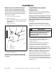
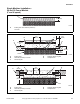
Pallet Jack Cover Plate Removal
(80 and 100 Pound Models Only)
Prior to installing an 80 and 100 pound machine, the
optional pallet jack cover plate can be removed in
preparation of re-installing to machine base frame
after machine installation.
1. Locate cover plate on back panel.
2. Remove back panel.
3. Remove all hardware holding cover plate on back
panel, refer to Figure 18. DO NOT DISCARD
HARDWARE.
4. Remove cover plate.
5. Re-install back panel.
NOTE: Refer to Pallet Jack Plate Installation to
install cover plate to machine base after machine
installation.
Single Machine Foundation
Requirements
A minimum 3500 psi (refer to rating per supplier)
reinforced concrete set on a prepared bed is required
for all new machine installations.
NOTE: Do not mount on wooden floors, tile floors,
elevated floor levels, stacked multiple base frames,
or over basements or crawl spaces because of the
high extract speed and the G-forces exerted. For 80
pound models and larger, do not mount on metal
base frames.
Thoroughness of detail must be stressed with all
foundation work to ensure a stable unit installation,
eliminating possibilities of excessive vibration during
extract.
For new foundations a mounting bolt template or an
elevated metal base frame is available at extra cost.
For all installations a concrete hardware kit is
available at extra cost.
The machine must be anchored to a smooth level
surface so that the entire base of the machine is
supported and rests on the mounting surface.
IMPORTANT: Do not permanently support the
machine on only four points with spacers. Grouting
is required and spacers must be removed.
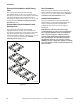
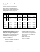
Machine Installation with Existing Floor
The existing floor slab must meet minimum
requirements shown in Table 13 per machine model.
The floor must be reinforced concrete without voids
under slab. If the floor meets these requirements and
an elevated pad is NOT desired, refer to Figures 20,
23, 32, and 35 and proceed to Machine Mounting and
Grouting section.
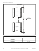
CHM2400N
1 Nut
2 Stud
3 Cover Plate
4 Back Panel
Figure 18
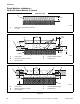
CHM2400N
2
1
3
1
4
To reduce the risk of fire, serious injury,
property damage and/or death, install the
machine on a level (within 3/8 inch),
uncovered concrete floor of sufficient
strength at grade.
W787
WARNING