USER GUIDE Publication AP6822
Limited One Year Warranty This product is warranted to be free from defects in materials or workmanship for period of one year from the date of purchase by the original owner. To ensure a high level of performance and reliability for which this equipment has been designed and manufactured, read this User Guide before operating.
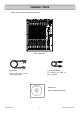
PACKED ITEMS Check that you have received the following: MIC MIC LINE MIC LINE MIC LINE MIC LINE ST RTN MIC LINE 2TRK RTN L L R R R L/M 2 3 4 5 6 INSERT INSERT INSERT INSERT INSERT ALT OUT L R LINE 1 INSERT REC OUT L L/M ST1 IN L/M ST2 IN R INSERT L AUX2 OUT INSERT R AUX3 OUT MONO OUT MAIN OUT L L/M ST3 IN R AUX1 OUT ST4 IN R R R PHONES AUX4 OUT 0 20 10 GAIN 0 20 10 10 30 GAIN 0 MIC LINE 40 50 -10 -6 63 26 30 63 26 100Hz HF GAIN 40 50 -10
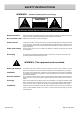
SAFETY INSTRUCTIONS WARNINGS - Read the following before proceeding : CAUTION ATTENTION: RISQUE DE CHOC ELECTRIQUE – NE PAS OUVRIR Read instructions: Retain these safety and operating instructions for future reference. Adhere to all warnings printed here and on the console. Follow the operating instructions printed in this User Guide. Do not remove cover: Operate the console with its covers correctly fitted.
SAFETY INSTRUCTIONS Important Mains plug wiring instructions The console is supplied with a moulded mains plug fitted to the AC mains power lead. Follow the instructions below if the mains plug has to be replaced.
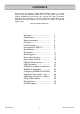
CONTENTS Thank you for purchasing your Allen & Heath ZED-14 mixer. To ensure that you get the maximum benefit from the unit please spare a few minutes familiarizing yourself with the controls and setup procedures outlined in this user guide. For further information please refer to the additional information available on our web site, or contact our technical support team. http://www.allen-heath.com Warranty ............................................. Packed Items.......................................
PANEL DRAWINGS This device complies with Part 15 of the FCC Rules. Operation is subject to the following two conditions: CAUTION (1) this device may not cause harmful interference, and (2) this device must accept any interference received, including interference that may cause undesired operation. RISK OF ELECTRIC SHOCK DO NOT OPEN AVIS: RISQUE DE CHOC ELECTRIQUE - NE PAS OUVRIR. ALLEN&HEATH CAUTION: FOR CONTINUED PROTECTION AGAINST RISK OF FIRE REPLACE FUSE WITH SAME TYPE AND RATING.
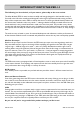
INTRODUCTION TO THE ZED-14 The following is a bit technical, so if you want to, please skip to the next section! The Allen & Heath ZED-14 mixer has been carefully and lovingly designed in the beautiful county of Cornwall in the UK and is manufactured alongside a wide range of professional audio mixing consoles.
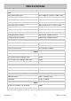
SPECIFICATIONS Operating Levels Input Mono channel (XLR) Input +6 to –63dBu for nominal (+17dBu in max) Mono channel Line Input (Jack socket) +10 to –26dBu (+30dBu maximum) Insert point (TRS Jack socket) 0dBu nominal +21dBu maximum Stereo Input (Jack sockets) 0dBu nominal (control = Off to +10dB) Stereo input (phono sockets) 0dBu nominal (control = Off to +10dB) Output L, R & Mono Outputs (L&R XLR, Mono Jack) 0dBu nominal. +21dBu maximum. Aux Outputs (Jack sockets) 0dBu nominal. +21dBu maximum.
465.00 Dimensions 40.43 93.00 110.69 384.00 Weight Unpacked 6.5kg (14.3lb) Packed 8.5kg (18.
BLOCK DIAGRAM MIC IN PP + - GAIN GAIN GAIN ON ON ON + - LR CHAN LR GAIN CHAN LR 100Hz GLOBAL 48V SWITCH GAIN R L LINE IN +48V STEREO CHANNEL 1 STEREO RETURN L R ST1/2/3/4 STEREO CHANNEL 2 L 2TRK RTN R STEREO CHANNEL 3 L REC OUT R CHAN HPF SUM + HM HF 3 BAND EQUALISER MONO CHANNEL INSERT LF HF SUM STEREO CHANNEL LF 2 BAND EQUALISER 2 TRK RTN TO MONITOR SELECTION USB RETURN FROM COMPUTER RECORD OUT FADER WIRE PAD SOLDER LINK STEREO AUX 3 AUX 2 AUX 1 BAL
MONO INPUT CHANNEL 1 Standard 3-Pin XLR socket wired as Pin 1=Chassis, Pin 2=hot (+), Pin 3=Cold (-). MIC 2 Line Input Jack Socket Standard 1/4” (6.25mm) Jack socket for balanced or unbalanced line level signals. Wired Tip=Hot(+), Ring=cold (-), Sleeve=Chassis. The Line input overrides the Mic input, so if you want to hear something plugged in to the xlr socket, make sure nothing is plugged into the Line input. 1 LINE 2 Mic Input Socket 1 3 INSERT Insert Jack Socket Standard 1/4” (6.
MONO INPUT CHANNELS 1TO 6 0 20 10 GAIN 6 10 30 0 MIC LINE 40 50 -10 -6 63 26 100Hz HF EQ The HF (High Frequency) equaliser affects the frequency response of the higher audible frequencies. The corner frequency of 12kHz is around 3dB from the maximum cut or boost of the circuit. It has plenty of gain and actually gives slightly more that the +/-15dB legend suggests. dBr 20.00 15.00 HF 12kHz 10.00 6 -15 500 5.00 +15 650 0.00 1k -5.00 200 -10.00 2k -15.00 3k 120Hz 4k HM -20.00 10.
MONO INPUT CHANNELS 1 TO 6 AUX1 9 Auxes 1 & 2 Each of these controls sends a signal to an auxiliary bus. The signal is sourced pre-fade which means that the level is independent of, and unaffected by the fader. Auxes 1 & 2 are primarily used for foldback monitoring purposes, as the fader does not affect the level. They can also be used as feeds for recording and are available sources to the USB interface for this purpose.
STEREO INPUT CHANNEL 7-8 1 Stereo Return Phono sockets This is an additional stereo input to the main stereo channel input (below). The gain is varied by the ST RTN control and this input can be sent to either the stereo channel or straight to the L R main bus, depending on the setting of the under-panel switch. These inputs are unbalanced. 2 Stereo Return Level control Adjusts the level of the stereo return input from off (fully attenuated) to maximum where it has 10dB of gain.
STEREO CHANNEL 7-8 8 8 STEREO AUX1 PRE OO +6 OO +6 OO +6 OO +6 AUX2 9 PRE Note: This can be useful when setting up a seperate stereo output from the main L R output using Auxes 1 & 2, possibly for recording. This can be selected to feed the USB output to create an independent stereo feed for recording using a computer. AUX3 POST AUX4 POST 10 9 Aux 1 & 2 sends These control the level of the signals sent to the Aux 1 & 2 buses.
STEREO INPUT CHANNELS 9-10, 11-12, 13-14 1 2 ST RTN 3 2TRK RTN -10 L L R R R R L/M L/M L/M L/M ST2 IN RTN 0 ST3 IN R 2TRK -5 -20 -10 USB -5 RTN 0 -30 10 ST4 IN R -20 5 OO ALT OUT L R RTN REC OUT L ST1 IN ST 4 -10 R USB -5 RETURN 0 SEND -20 5 -30 OO 10 ON ON To LR To 7-8 To LR To 9-10 5 -30 OO 10 ON To LR To 11-12 AUX1-2 5 AUX 3-4 LR PRE UP=LR post 1 Stereo Input Channel 7-8 This is stereo input channel 7-8 as described on pages 12 & 13.
USB & MASTER SECTION 1 2 AUX1 OUT INSERT L MAIN OUT 1 Aux output jack sockets Standard 1/4” jack sockets for Aux 1 to 4 outputs. Impedance balanced, nominal level = 0dBu. 2 Mix L R Insert jack sockets Standard 1/4” (6.25mm) Jack sockets for unbalanced insert send and return signals. Wired Tip = send, Ring = return, Sleeve = Chassis. Nominal level is 0dBu. 3 Main L R output xlr sockets Main left & right outputs. Impedance balanced signals, pin1 = chassis, pin2 = hot (+), pin3 = cold (-).
USB & MASTER SECTION PHONES 8 AUX4 OUT POWER 48V L +16 +9 +6 +3 0 -3 -6 -9 -12 -16 -20 -30 R PFL ACTIVE PHONES 9 MIN MAX AUX1 STEREO AUX2 8 2TRK RTN ALLEN&HEATH +16 +9 +6 +3 0 -3 -6 -9 -12 -16 -20 -30 PHANTOM POWER USB RTN 9 Monitor selector switches These 4 switches select the signal source for the headphones monitor and the meters. They work on a priority basis.
USB CONNECTION L/M L/M ST2 IN L/M ST3 IN R ST4 IN R AUX3 OUT MONO OUT R AUX4 OUT -10 USB -5 RTN 0 -10 USB -5 RETURN 0 SEND -20 5 POWER 5 -30 10 O AUX1-2 10 OO ON ON To LR To 9-10 AUX 3-4 To LR To 11-12 48V +16 +9 +6 +3 0 -3 -6 -9 -12 -16 -20 -30 LR PRE PHANTOM POWER UP=LR post -10 -5 ST3 -10 0 OO -5 0 IN -20 5 -30 10 ST4 -10 0 IN -20 5 O -5 5 -30 10 10 OO HF HF 12kHz 12kHz L PFL ACTIVE -15 +15 -15 +15 -15 LF LF 80Hz 80Hz +15 PHONES MI
cakewalk SONAR LE DIGITAL AUDIO WORKSTATION SONAR LE Overview. SONAR LE is a software application from Cakewalk and is included free of charge with your new ZED mixing console. SONAR LE is a powerful first step into the world of sequencing and hard disk recording on the Windows platform. You’ll be able to record from your ZED mixer, create tracks and arrange songs, then play back to your ZED mixer via the USB port. You can decide whether the SONAR family of products is right for you.
System Requirements. System Requirements Minimum Recommended Windows XP Windows XP/Vista/Vista x64 Intel® Pentium® 4 1.3 GHz, or AMD™ Athlon XP 1500+ or higher Intel® Pentium® 4 2.
Next, fire up SONAR LE. Click Options/Audio and click on the Drivers tab. The Input drivers are the audio sources to the computer, here we have enabled the USB Audio Dewhich is the ZED mixing console USB device, and disabled the audio from the soundcard in the pc. So the computer is set up to receive audio from ZED. vice The Output Drivers are the audio outputs from the computer.
To record the audio on tracks 1 & 2, click the R buttons so they light up red, then the record button (circle) on the transport controls on the top icon toolbar. (Or select larger transport controls from Views). The audio wave profile will show in the track panes. Click stop (Square) when finished. To listen to the recording, click rewind, then de-select the input echo buttons (to the right of the R buttons. Also disarm the tracks by deselecting the R buttons.
LIVE SETUP Powered PA Speakers CD Player CD Effects Units Line or Stereo inputs fx Mic Inputs Powered Stage Monitors MIC MIC LINE MIC LINE 1 LINE 2 INSERT MIC LINE 3 INSERT MIC LINE 4 INSERT 6 2TRK RTN REC OUT ALT OUT L L L L R R R R L/M L/M L/M L/M LINE 5 INSERT ST RTN MIC ST1 IN ST2 IN ST4 IN ST3 IN AUX1 OUT INSERT L AUX2 OUT INSERT R MAIN OUT L R AUX3 OUT MONO OUT INSERT INSERT R R R R PHONES AUX4 OUT GAIN 0 20 10 0 20 10 10 30 0 40 MIC
RECORDING SETUP Main Studio Speakers KT-88 Alt Studio Speakers Effects Units fx Amp Mic Inputs Line Inputs MIC MIC LINE MIC LINE MIC LINE MIC LINE ST RTN MIC LINE 1 2 3 4 5 6 INSERT INSERT INSERT INSERT INSERT REC OUT ALT OUT L L L R R R R L/M L/M L/M L/M LINE INSERT 2TRK RTN L ST1 IN ST2 IN R ST4 IN ST3 IN R R AUX1 OUT INSERT L AUX2 OUT INSERT R AUX3 OUT MONO OUT MAIN OUT L Powered Monitor R R PHONES AUX4 OUT GAIN 0 20 10 0 20 10 10 30 0 40
USING USB FOR EFFECTS ST2 IN ST3 IN R 5 ST4 IN R R 4 -10 USB -5 RTN 0 -10 6 USB -5 RETURN 0 SEND -20 5 5 -30 10 O AUX1-2 10 OO ON ON To LR To 9-10 AUX 3-4 To LR To 11-12 3 7 LR PRE PHANTOM POWER 2 UP=LR post -10 -5 ST3 -10 0 IN 5 -15 IN 5 -30 12kHz 12kHz +15 LF 80Hz 80Hz +15 -15 +15 AUX1 +6 +6 OO = L AUX3 POST POST AUX4 POST POST +6 OO = L MUTE PK ! +6 OO AUX4 BAL R +6 OO +6 O +6 OO +6 OO +6 PRE AUX3 +6 O 12 OO AUX2 PR
WIRING NOTES PROCESSOR Insert cable wiring RETURN S INSERT T OUT T R S R SEND GROUND RETURN SEND S T R IN LINK RING TO SLEEVE TO UNBALANCE Y-Adapter Y-Adapter RCA phono jacks 2 Outputs to 1 Input adapter 1 Output to 2 Inputs RCA PHONO CABLE UNBALANCED No ! UNBALANCED INSTRUMENT CABLE UNBALANCED BALANCED TRS JACK CABLE BALANCED Sleeve=ground Sleeve=ground Ring=cold (-) Ring=cold (-) Tip=hot (+) TO INPUT Tip=hot (+) 2=hot (+) 1=ground BALANCED MIC CABLE 1=ground BALANCED
PRODUCT SUPPORT Investigate ALLEN & HEATH’s other ranges at www.allen-heath.com Large Live Sound mixers — iLive digital, ML and GL Series Small Format Live Sound mixers — ZED, MixWizards and PA Series DJ products — Xone Series Sound Management Series — iDR Series Registering your product Thank you for buying the Allen & Heath ZED-14 mixer. you enjoy many years of faithful service with it. We hope that you are happy with it and that Please go to www.allen-heath.com/register.