USER GUIDE Publication AP8509 Allen & Heath 1 XONE:K2 User Guide
Limited One Year Warranty This product is warranted to be free from defects in materials or workmanship for period of one year from the date of purchase by the original owner. To ensure a high level of performance and reliability for which this equipment has been designed and manufactured, read this User Guide before operating.
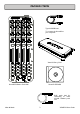
PACKED ITEMS Type A-B USB Lead To connect the Xone:K2 to your computer.
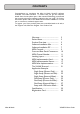
CONTENTS Congratulations on purchasing the Allen & Heath Xone:K2 software controller and audio interface. To ensure that you get the maximum benefit from the unit please spare a few minutes familiarizing yourself with the controls and setup procedures outlined in this user guide. For further information please refer to the additional information available on our web site, or contact our technical support team. To register your Xone product please visit www.allen-heath.co.
PRODUCT OVERVIEW The XONE:K2 is a software controller and audio interface designed to work with all DAW applications that implement MIDI.
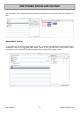
SOFTWARE INSTALLATION MAC The Xone:K2 is class compliant and enumerates as a MIDI device and four-channel audio device on a Mac. AGGREGATE AUDIO To aggregate two Xone:K2 units together, click the ‘+’ button in the bottom left of the audio devices window to create a new aggregate audio device. Next, in the right hand side of the window, select both instances of the K2 and you will essentially create one device with eight outputs.
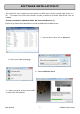
SOFTWARE INSTALLATION PC The Xone:K2 is class compliant and enumerates as a MIDI device and two-channel audio device on a PC. To benefit from the full four-channels of audio provided, the Xone:K2 ASIO Driver must be installed. Software Installation (Windows 2000, XP, Vista and Windows 7) Follow the procedure described below to install the USB audio and MIDI drivers: 1—Open the Drivers folder and run Setup.
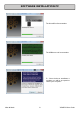
SOFTWARE INSTALLATION PC The Xone:K2 will now initialise. The USB drivers will now initialise. 5— Once the driver installation is complete you will be prompted to reboot your computer.
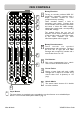
MIDI CONTROLS 1 1 2 3 2 4 6 Rotary Potentiometers These controls ar e standar d potentiometers with end stops. Turning a pot from left to right will send MIDI messages with a unique CC number and a control value from 0 to 127. 3 Pot Switches Each rotary potentiometer has a switch with tri-colour illumination below it. 4 Linear Faders Moving a linear fader will send a MIDI message with a unique CC number and a control value from 0 (bottom) to 127 (top).
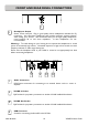
FRONT AND REAR PANEL CONNECTORS 1 1 Headphones Output Stereo 3.5mm mini-jack. Plug in good quality stereo headphones intended for DJ monitoring. Use closed-ear headphones that provide maximum acoustic isolation when cueing your sources. We recommend that you use high quality headphones rated between 30 to 100 ohms impedance. 8 ohm headphones are not recommended. Warning ! To avoid damage to your hearing do not operate the headphones or sound system at excessively high volume.
MIDI CHANNEL NUMBER By default the MIDI Channel number is set to 15 to prevent control interaction with Xone DB series mixers which default to channel 16. To change the MIDI channel number on your XONE:K2, you must first enter setup mode. 1 Setup Mode To enter setup mode, press and hold down the encoder [1] then power up by plugging the USB cable to your PC/Mac, (or RJ45 lead if powered from X-LINK). The switch matrix LED’s will flash RED three times to indicate that the K2 has entered setup mode.
LATCHING LAYERS Latching Layers’ provide embedded layer control via the ‘LAYER’ button on the Xone:K2. If Latching Layers are on, the LAYER switch is used to toggle between the RED, AMBER then GREEN layers. From this, if the LAYER switch is RED, any switch used on this layer will illuminate RED; if the layer switch is AMBER, then any switch used on this layer will illuminate AMBER etc. To change the Latching Layers system on your XONE:K2, you must first enter setup mode.
LATCHING LAYERS 1 2 3 4 5 If Latching Layers are ‘on’ (states [2], [3], [4] and [5]), the LAYER switch is used to toggle between the three layers. LATCHING LAYER OPTIONS Use the rotary action of the Setup encoder to select between the Latching Layer options. The Latching Layer states shown above are described as follows: 1 LATCHING LAYERS OFF - In this state, Latching Layers are disabled and the ‘Layer’ button is available for user configuration.
MIDI IMPLEMENTATION SEND ▼E3 ▼F3 ▼F#3 ▼G3 ◄►CC0 ◄►CC1 ◄►CC2 ◄►CC3 ▼E6 ▼F6 ▼F#6 ▼G6 ◄►CC22 ◄►CC23 ◄►CC24 ◄►CC25 ▼E9 ▼F9 ▼F#9 ▼G9 ◄►CC44 ◄►CC45 ◄►CC46 ◄►CC47 ◄►CC4 ◄►CC5 ◄►CC6 ◄►CC7 ◄►CC26 ◄►CC27 ◄►CC28 ◄►CC29 ◄►CC48 ◄►CC49 ◄►CC50 ◄►CC51 ■ C3 ■ C#3 ■ D3 ■ D#3(Eb3) ■ C6 ■ C#6 ■ D6 ■ D#6(Eb6) ■ C9 ■ C#9 ■ D9 ■ D#9(Eb9) ◄►CC8 ◄►CC9 ◄►CC10 ◄►CC11 ◄►CC30 ◄►CC31 ◄►CC32 ◄►CC33 ◄►CC52 ◄►CC53 ◄►CC54 ◄►CC55 ■ G#2 ■ A2 ■ A#2(Bb2) ■ B2 ■ G#5 ■ A5 ■ A#2(Bb
MIDI IMPLEMENTATION SEND ◄►CC12 ◄►CC13 ◄►CC14 ◄►CC15 ◄►CC34 ◄►CC35 ◄►CC36 ◄►CC37 ◄►CC56 ◄►CC57 ◄►CC58 ◄►CC59 ■ E2 ■ F2 ■ F#2 ■ G2 ■ E5 ■ F5 ■ F#5 ■ G5 ■ E8 ■ F8 ■ F#8 ■ G8 ◄►CC16 ◄►CC17 ◄►CC18 ◄►CC19 ◄►CC38 ◄►CC39 ◄►CC40 ◄►CC41 ◄►CC60 ◄►CC61 ◄►CC62 ◄►CC63 ■ C2 ■ C#2 ■ D2 ■ D#2(Eb2) ■ C5 ■ C#5 ■ D5 ■ D#5(Eb5) ■ C8 ■ C#8 ■ D8 ■ D#8(Eb8) ■ G#1 ■ A1 ■ A#1(Bb1) ■ B1 ■ G#4 ■ A4 ■ A#4(Bb4) ■ B4 ■ G#7 ■ A7 ■ A#7(Bb7) ■ B7 Allen & Heath 15 LATCHING LAYER
MIDI IMPLEMENTATION SEND ■ E1 ■ F1 ■ F#1 ■ G1 ■ E4 ■ F4 ■ F#4 ■ G4 ■ E7 ■ F7 ■ F#7 ■ G7 ■ C1 ■ C#1 ■ D1 ■ D#1(Eb1) ■ C4 ■ C#4 ■ D4 ■ D#4(Eb4) ■ C7 ■ C#7 ■ D7 ■ D#7(Eb7) ■ C0 ▼ C#0 ▼ D0 ■ D#0(Eb0) ◄►CC20 ◄►CC21 ■ E0 ▼ F0 ◄►CC42 ■ G#0 ▼ A0 ◄►CC68 Allen & Heath ▼ F#0 LATCHING LAYERS OFF LATCHING LAYERS ON LATCHING LAYERS OFF LATCHING LAYERS ON LATCHING LAYERS OFF ■ G0 ◄►CC43 ▼ A#0(Bb0) ■ B0 LATCHING LAYERS ON ◄►CC69 16 XONE:K2 User Guide
MIDI IMPLEMENTATION RETURN ▼E3 ▼F3 ▼F#3 ▼G3 ▼E6 ▼F6 ▼F#6 ▼G6 ▼E9 ▼F9 ▼F#9 ▼G9 ■ C3 ■ C#3 ■ D3 ■ D#3(Eb3) ■ C6 ■ C#6 ■ D6 ■ D#6(Eb6) ■ C9 ■ C#9 ■ D9 ■ D#9(Eb9) ■ G#2 ■ A2 ■ A#2(Bb2) ■ B2 ■ G#5 ■ A5 ■ A#5(Bb5) ■ B5 ■ G#8 ■ A8 ■ A#8(Bb8) ■ B8 ■ E2 ■ F2 ■ F#2 ■ G2 ■ E5 ■ F5 ■ F#5 ■ G5 ■ E8 ■ F8 ■ F#8 ■ G8 Allen & Heath 17 XONE:K2 User Guide
MIDI IMPLEMENTATION RETURN ■ C2 ■ C#2 ■ D2 ■ D#2(Eb2) ■ C5 ■ C#5 ■ D5 ■ D#5(Eb5) ■ C8 ■ C#8 ■ D8 ■ D#8(Eb8) ■ G#1 ■ A1 ■ A#1(Bb1) ■ B1 ■ G#4 ■ A4 ■ A#4(Bb4) ■ B4 ■ G#7 ■ A7 ■ A#7(Bb7) ■ B7 ■ E1 ■ F1 ■ F#1 ■ G1 ■ E4 ■ F4 ■ F#4 ■ G4 ■ E7 ■ F7 ■ F#7 ■ G7 ■ C1 ■ C#1 ■ D1 ■ D#1(Eb1) ■ C4 ■ C#4 ■ D4 ■ D#4(Eb4) ■ C7 ■ C#7 ■ D7 ■ D#7(Eb7) ■ C0 ■ D#0(Eb0) ■ E0 ■ G0 ■ G#0 ■ B0 Allen & Heath 18 XONE:K2 User Guide
MIDI NOTE IMPLEMENTATION TABLE DEC HEX NOTE DECIMAL HEX NOTE DECIMAL HEX NOTE 0 00 C-1 24 18 C1 48 30 C3 1 01 C#-1 25 19 C#1 49 31 C#3 2 02 D-1 26 1A D1 50 32 D3 3 03 D#-1 27 1B D#1 51 33 D#3 4 04 E-1 28 1C E1 52 34 E3 5 05 F-1 29 1D F1 53 35 F3 6 06 F#-1 30 1E F#1 54 36 F#3 7 07 G-1 31 1F G1 55 37 G3 8 08 G#-1 32 20 G#1 56 38 G#3 9 09 A-1 33 21 A1 57 39 A3 10 0A A#-1 34 22 A#1 58 3A A#3 11 0B B-1 35 23
MIDI NOTE IMPLEMENTATION TABLE DECIMAL HEX NOTE DECIMAL HEX NOTE DECIMAL HEX NOTE 72 48 C5 96 60 C7 120 78 C9 73 49 C#5 97 61 C#7 121 79 C#9 74 4A D5 98 62 D7 122 7A D9 75 4B D#5 99 63 D#7 123 7B D#9 76 4C E5 100 64 E7 124 7C E9 77 4D F5 101 65 F7 125 7D F9 78 4E F#5 102 66 F#7 126 7E F#9 79 4F G5 103 67 G7 127 7F G9 80 50 G#5 104 68 G#7 81 51 A5 105 69 A7 82 52 A#5 106 6A A#7 83 53 B5 107 6B B7 84 54 C6 10
THE X:LINK PROTOCOL The X:LINK protocol is a proprietary Allen and Heath protocol for connection between X:LINK enabled products. XONE:K2 X:LINK In the case of the XONE:K2, X:LINK provides power and MIDI data transfer between two units. NOTE: X:LINK does not include the transfer of audio. Use the provided RJ45 cable to link the OUT connection on one unit to the IN connection of the other. The unit wired to the IN connection should be the unit that is connected to the PC/Mac (see below).
APPLICATION EXAMPLES SINGLE SETUP (PHONES ONLY) The above diagram shows a basic setup using one Xone:K2 (front and rear panels are both shown). In this application the XONE:K2 is being used with headphones only. PC DRIVER TYPE In this particular application, as only the headphones are in use, it is possible to use the WDM (Windows Device Manager) driver or the supplied ASIO driver. The WDM driver will default to Soundcard Output 1-2 which feeds the headphones.
APPLICATION EXAMPLES SINGLE SETUP (PHONES AND MIX) The above diagram shows a basic setup using one Xone:K2 (front and rear panels are both shown). In this application, the XONE:K2 Master output is wired to a speaker system. PC DRIVER TYPE In this particular application, as the Master Output and the headphones are in use, the ASIO driver must be employed. MAC The XONE:K2 is Class Compliant and does not need a specific driver.
APPLICATION EXAMPLES SINGLE SETUP (EXTERNAL MIXER) The diagram shows a setup using one XONE:K2 and a twochannel analogue mixer. The front and rear panels of the XONE:K2 are shown, joined by the dashed line. In this configuration, the XONE:K2 Master Output is connected to one channel on the mixer using RCA cables. The XONE:K2 Headphone Output is connected to the other channel on the mixer using a 3.5mm jack to dual RCA lead.
APPLICATION EXAMPLES DUAL SETUP (PHONES ONLY) The above diagram shows a setup using two Xone:K2s. The front and rear panels are shown on the ’Master’ unit, joined by the dashed line. In this configuration, the XONE:K2’s are linked together using the X:LINK bus. This gives twice the amount of control but still only utilises one USB port. For more information on the X:LINK setup see THE X:LINK PROTOCOL on Page 18.
APPLICATION EXAMPLES DUAL SETUP (PHONES AND MIX) The above diagram shows a setup using two Xone:K2s. The front and rear panels are shown on the ’Master’ unit, joined by the dashed line. In this configuration, the XONE:K2’s are linked together using the X:LINK bus. This gives twice the amount of control but still only utilises one USB port. The XONE:K2 Master output is wired to a speaker system. For more information on the X:LINK setup see THE X:LINK PROTOCOL on Page 18.
APPLICATION EXAMPLES DUAL SETUP (EXTERNAL MIXER) The diagram shows a setup using two Xone:K2s and a fourchannel analogue mixer. The front and rear panels of the XONE:K2’s are shown, joined by the dashed line. In this configuration, the first XONE:K2 Headphone Output is connected to channel one on the mixer using a 3.5mm jack to dual RCA lead. The Master Output of this XONE:K2 is connected to channel two on the mixer using RCA cables.
APPLICATION EXAMPLES CONNECTING TO A DB SERIES MIXER The diagram shows a setup using two Xone:K2s and a XONE DB Series mixer. In this configuration, the XONE:K2 units are connected via their X:LINK sockets. The OUT connection of the K2 on the left is connected to the IN connection of the K2 on the right. The OUT connection of the K2 on the right is connected to the X:LINK socket on the XONE DB Series mixer. In this configuration, power to the two Xone K2 units is supplied over X:LINK.
SPECIFICATIONS Dimensions and Weights Xone:K2 Carry Case Packed Width 135 mm(5.3”) 170 mm(6.7”) 185 mm(7.3”) Height 30 mm(1.2”) 70 mm(2.8”) 78 mm(3”) Depth 358 mm(14”) 392 mm(15.4”) 426 mm(16.8”) Weight 1.0kg (2.2lbs) 0.4kg (0.9lbs) 1.5kg (3.3lbs) Frequency Response 44.1kHz 20Hz to 20kHz +0/–0.4 dB THD + N 0.01% typical Maximum Output Level +6 dBu Dynamic Range Output 96 dB Registering your product Thank you for buying the Allen & Heath Xone:K2 software controller and audio interface.
Allen & Heath 30 XONE:K2 User Guide