USER GUIDE Publication AP7265 Allen & Heath XONE:4D User Guide
Limited One Year Warranty This product is warranted to be free from defects in materials or workmanship for period of one year from the date of purchase by the original owner. To ensure a high level of performance and reliability for which this equipment has been designed and manufactured, read this User Guide before operating.
CONTENTS Congratulations on purchasing the Allen & Heath Xone:4D performance DJ mixer. To ensure that you get the maximum benefit from the unit please spare a few minutes familiarising yourself with the controls and setup procedures outlined in this user guide. For further information please refer to the additional information available on our web site, or contact our technical support team. http://www.xone.co.uk Warranty ............................................. Packed Items ..........................
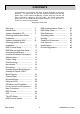
PACKED ITEMS Check that you have received the following: Xone:4D mixer Check that the rear panel optical in/out blank plugs are fitted. Mains Lead Check that the correct mains plug is fitted. Spare knobs and buttons Rack Ears + fixings. For mounting the 4D in a 19” rack. 6x M4x10mm screws Type A-B USB Lead To connect the Xone:4D to your computer. Allen & Heath Safety Sheet Important ! Read this sheet before starting. Retain for future reference.
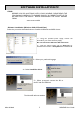
SOFTWARE INSTALLATION PC STOP! BEFORE YOU DO ANYTHING WITH YOUR XONE:4D, PLEASE READ THE FOLLOWING CAREFULLY TO ENSURE YOUR PC IS CORRECTLY SET UP TO BE USED WITH THE DEVICE. PLEASE DOWNLOAD THE LATEST DRIVERS FROM: www.xone.co.uk/4d Software Installation (Windows 2000, XP and Vista) Follow the procedure described below to install the USB audio and MIDI drivers: 1— Using the provided power supply, connect the Xone:4D to your mains electricity supply. Do not connect the 4D to the PC at this time.
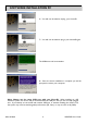
SOFTWARE INSTALLATION PC 6— You will now be asked to unplug your Xone:4D 7— You will now be asked to plug in your Xone:4D again. The USB drivers will now initialise. 8— Once the driver installation is complete you will be prompted to reboot your computer. Note: Always use the same USB port with your Xone:4D. When installing on a MS Windows system, the drivers will be associated with the USB port that you are currently plugged into.
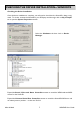
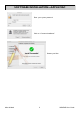
CHECKING THE DRIVER INSTALLATION—WINDOWS Checking the Driver Installation Once the driver installation is complete, you will need to check that the Xone:4D is being recognised. To do this, connect the Xone:4D to your PC/laptop and then right click on My Computer to open the System Properties window. Select the Hardware tab then click on Device Manager Expand the Sound, Video and Game Controllers section to reveal the WDM audio and MIDI drivers for the Xone:4D.
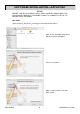
SOFTWARE INSTALLATION—APPLE MAC STOP! BEFORE YOU DO ANYTHING WITH YOUR XONE:4D, PLEASE READ THE FOLLOWING CAREFULLY TO ENSURE YOUR PC IS CORRECTLY SET UP TO BE USED WITH THE MIXER. Mac OSX Open the Xone_4D_Driver_x.x.x.dmg to reveal the window shown. Click on the Xone:4D mpkg file to launch the driver installation. Click on “Continue”. Select install location and then click “Install”.
SOFTWARE INSTALLATION—APPLE MAC Enter your system password. Click on “Continue Installation”. Restart your Mac.
CHECKING THE DRIVER INSTALLATION—APPLE MAC Checking the Driver Installation Once the driver installation is complete, you will need to check that the Xone:4D is being recognised. To do this, connect the Xone:4D to your Mac and then select: Mackintosh HD Applications Utilities Audio MIDI Setup Now select the Audio tab and in the “Properties For” dropdown box select Allen & Heath Xone:4D. In the Audio Input section, the number of channels should be seen as 10, running at 24 bit.
MIDI CHANNEL SETUP MIDI Channel Number The MIDI channel number will default to channel 16, but can be changed to any channel between 1 and 16. To change the MIDI channel number and MIDI map: 1. Hold down the switch on the encoder shown in the diagram 2. Turn on the Xone:4D 3. At the end of the start up sequence, when the illuminated switches have flashed three times, release the switch on the encoder.
MIDI MAP AND LIGHT PIPE SETUP Changing the MIDI Map Once the MIDI channel number has been stored, the illuminated switch to the far right of the unit will flash indicating that the MIDI map may now be selected. The following examples are in relation to the left-hand MIDI pod on the Xone:4D. Map 1 (Traktor default) The first switch (far left) is used to select MIDI Map 1. In this map the top row of encoders send ‘Note On’ messages upon rotation (see MIDI Control Section p39).
SOUNDCARD ARCHITECTURE ANALOGUE INPUTS: The analogue inputs are sourced from the input channels on the Xone:4D as follows: Channel Soundcard Input Selectable From 1 1/2 Mic or Channel 1 (Pre or Post Fader) 2 3/4 FX2 or Channel 2 (Pre or Post Fader) 3 4 5/6 7/8 FX1 or Channel 3 (Pre or Post Fader) Mix or Channel 4 (Pre or Post Fader) DIGITAL INPUTS: The SPDIF digital inputs are sourced directly from the digital input sockets on the rear of the Xone:4D.
SOUNDCARD SOFTWARE DESCRIPTION SOFTWARE DESCRIPTION The inputs and outputs of the soundcard have a description within the software being used. Below are the descriptions used in Ableton and Traktor.
ABLETON SET UP Turn on your Xone:4D, launch your Ableton software and open the Preferences window. 1— In the Preferences window select the Audio tab. Change the driver type to ASIO and set the Audio Device to Xone:4D USB ASIO driver In the Settings section click on the Input Config button. 2— Select the Stereo options and de-select the Mono options. You must click OK for the changes to take effect. Now, in the Settings section of the Audio tab, click on the Output Config button.
TRAKTOR SET UP Turn on your Xone:4D, launch your Traktor software and open the Preferences window. 1— In the Preferences window, expand the Audio Setup section and select Soundcard. Set the Audio Device to Xone:4D USB ASIO driver’ Now select Input Routing. 2— In the Input Routing section, assign the Xone:4D analogue or digital inputs to the required deck. Now select Output Routing. 3— In the Output Routing section, first make sure that the Mixer Mode is set to External.
PANEL DRAWINGS CAUTION INPUT 4 WARNING: FOR CONTINUED PROTECTION AGAINST RISK OF FIRE REPLACEFUSEWITH SAMETYPEAND RATING. ATTENTION: REMPLACERPARUN FUSIBLE STRICTEMENT IDENTIQUEEN VALEURS. WARNING: THIS APPARATUS MUST BEEARTHED. TOREDUCETHERISK OF FIREORELECTRIC SHOCK DONOT EXPOSEAPPARATUS TORAIN ORMOISTURE.
INTRODUCTION TO THE XONE:4D Welcome to the Allen & Heath Xone:4D digital DJ workstation. This system has been designed with the help of some of the world’s most cutting edge DJs to provide a seamless integration of traditional and computer-based audio replay systems. The Xone:4D comprises three main sections: MIXER— The mixer is based on the award-winning Allen & Heath Xone:92. It lets you mix a combination of vinyl, CD and other sources through 4 stereo channels to its main mix and monitor outputs.
DESCRIPTION MIXER Each of the 4 channels can select one of 3 sources: phono, line or soundcard audio as shown. RIAA phono preamps are available on channels 1, 2 and 3. These may be changed to line input by resetting an internal jumper link if required. Level may be adjusted over a +/- 10dB range if the signal reads too high or low on the channel meters. The 3-band EQ provides a safe amount of boost but full cut (kill) for dramatic effect. A mic input with level and 2-band EQ routes direct to the main mix.
DESCRIPTION MIDI CONTROL MIDI (musical instrument digital interface) is a standardised protocol for communication between electronic music devices as well as between those devices and computers. Two identical banks of MIDI controls are provided on either side of the mixer section. These bring control of remote performance equipment such as computer-based sound manipulation and sequencing, samplers, effects and even lighting right to the mixer control surface.
SOUNDCARD INPUT BLOCK DIAGRAM SOUNDCARD IN 9/10 Auto-Sense ADC Ch4 Pre Fade Main Mix FX1 Send Ch3 Pre Fade Microphone Input Ch2 Pre Fade FX2 Send ADC ADC Ch1 Pre Fade ADC USB2.0 IN 7/8 IN 5/6 IN 3/4 IN 1/2 Post-Fade Channel Send Note: The pre-fade channel send is sourced after the phono/ line input switch. From this, the soundcard input can only be routed back to software when the pre/ post switch is set to post.
SOUNDCARD OUTPUT / MIDI BLOCK DIAGRAM SOUNDCARD OUT 9/10 MODE 1 1 STEREO IN / 3 STEREO OUT SOUNDCARD OUT 5 DAC 6 4 DAC 1 OUT SPDIF IN OPTICAL COAX OPTICAL COAX 3 1 DAC DAC DAC 2 Phono Input Phono Input 3 PHONO LINE SOUNDCARD Line Input DAC 2 LINE Line Input DAC USB2.
MIXER SECTION — CHANNEL INPUT 1 2 1 3 2 FX 1-2 send controls These controls adjust the signal level that is sent from each channel to the two FX mix busses. These signals will appear at the RCA sockets on the rear of the unit. FX1 PRE switch determines whether the FX1 send signal is affected by the channel fader. When pressed the signal is prefader, when released post-fader. FX1 can also be sent to the input of the soundcard for processing or recording by the PC (see Soundcard Mode for details).
MIXER SECTION — CHANNEL INPUT 3 3 4 Channel Level Control This control has a range of +/- 10dB either side of the 0dB centre position. Use it to adjust the signal level of an audio source to give a nominal 0dB reading on the channel meter, with the peak level at or below +6dB. Turn LEVEL down if the +10 peak meter starts flashing.
MIXER SECTION — CHANNEL INPUT 7 Channel Meter Displays the channel signal level. It is postEQ and pre-fader. This means it is not affected by the EQ or fader position. The channel level control should be set so that the meter averages around ‘0’ with loudest peaks no higher than ‘+6’. Turn down the level control if the +10 peak indicator lights. 8 Channel Fader A high quality, smooth travel dual-rail fader adjusts the channel signal level from fully off to fully on.
MIXER SECTION — MIX AND MONITOR 1 Mix / Monitor Meters The main meters follow the selected monitor source. The meter reads ‘0’ for an XLR output of +4dBu. The mixer should be operated with these meters averaging around ‘0’ with loudest peaks no higher than ‘+6’. 2 Record to FX2 Switch Selecting this switch will send the pre-fade mix output to the FX2 Send RCA sockets on the rear of the mixer.
MIXER SECTION — MIX AND MONITOR 7 8 Cue / Add Mix Control Allows the main mix output to be added to the CUE signal. Turned fully anti-clockwise, only the active CUE signal is heard through the headphones when selected. Gradually turning clockwise introduces the main mix output to the headphones, adding to the active CUE. This does not affect the meters. Headphones Level Control Adjusts the level of the headphones signal.
MIXER SECTION — FILTERS and LFO 1 LFO Tap Tempo button Tap the tap tempo button in time with the beat to set the frequency of the LFO. 2 LFO Depth control When assigned, the LFO modulates the filter with a cyclic frequency sweep effect in time to the beat set using the tap tempo button. The depth control adjusts how much effect the LFO has on the filter effect from fully off to very deep. For more information, including the LFO editor function, see page 37.
FILTER 1 MIX BUS FILTER 2 MIX BUS MAIN LR MIX BUS MIXER SECTION — FX RTN & CROSSFADER XFADE ON XFADE CURVE CROSSFADER X Y FILTER 2 MIX FILTER 1 MIX LFO DEPTH FILTER / XFADE SELECT FROM INPUT CHANNEL FILTER 1 TAP TEMPO FILTER 2 DC 1 X1 2Y VCA OFF VCA 4 3 1 FX Return Controls These controls route the incoming signal from the stereo FX1 and FX2 Return RCA connectors on the rear panel to the mix. They adjust how much return signal is added to the mix.
FRONT CONTROLS & CONNECTORS LF -12 HF + 12 -12 PHONES 1 1 2 3 4 Allen & Heath LEVEL + 12 0 10 MIC 2 3 4 Headphones Outputs Stereo 1/4” TRS jack and 3.5mm mini-jack. Plug in good quality stereo headphones intended for DJ monitoring. Use closed-ear headphones that provide maximum acoustic isolation when cueing your sources. We recommend that you use high quality headphones rated between 30 to 100 ohms impedance. 8 ohm headphones are not recommended.
REAR CONNECTORS 3 CAUTION INPUT 4 WARNING: FORCONTINUED PROTECTION AGAINST RISK OF FIRE REPLACEFUSEWITH SAMETYPEAND RATING. ATTENTION: REMPLACERPARUN FUSIBLE STRICTEMENT IDENTIQUEEN VALEURS. WARNING: THIS APPARATUS MUST BEEARTHED. TOREDUCETHERISK OF FIREORELECTRIC SHOCK DONOT EXPOSEAPPARATUS TORAIN ORMOISTURE.
REAR CONNECTORS CAUTION INPUT 4 WARNING: FORCONTINUED PROTECTION AGAINST RISK OF FIRE REPLACEFUSEWITH SAMETYPEAND RATING. ATTENTION: REMPLACERPARUN FUSIBLE STRICTEMENT IDENTIQUEEN VALEURS. WARNING: THIS APPARATUS MUST BEEARTHED. TOREDUCETHERISK OF FIREORELECTRIC SHOCK DONOT EXPOSEAPPARATUS TORAIN ORMOISTURE.
REAR CONNECTORS 13 14 CAUTION INPUT 4 WARNING: FORCONTINUED PROTECTION AGAINST RISK OF FIRE REPLACEFUSEWITH SAMETYPEAND RATING. ATTENTION: REMPLACERPARUN FUSIBLE STRICTEMENT IDENTIQUEEN VALEURS. WARNING: THIS APPARATUS MUST BEEARTHED. TOREDUCETHERISK OF FIREORELECTRIC SHOCK DONOT EXPOSEAPPARATUS TORAIN ORMOISTURE.
MIXER SECTION — BPM COUNTER 1 1 BPM Display Displays the tempo of an analysed piece of music, rounded up to the nearest whole number. On power-up, and when the detector is reset, the display will show a line of three dashes. When an audio source is routed to the auto beat detector, a dot in the bottom right hand corner will flash to indicate that BPM analysis is taking place. 2 The display can also show the BPM to the nearest decimal place by pressing and holding the TAP button.
MIXER SECTION — BPM COUNTER 4 BPM Tap Tempo Button This control is used to tap in a beat manually at any speed between 70 and 400 BPM. The taps are averaged, so the greater number of taps the more accurate the result. The tap button can also be used as a guide for the auto beat detector on complex rhythms by helping the analyser lock onto the correct pattern, for instance drum ‘n bass tracks can occasionally be displayed at half the actual BPM.
MIXER SECTION — LFO 6 LFO Tap Tempo button Tapping this button will set the speed of the LFO (low frequency oscillator) within the range of 0.25Hz - 3.33Hz (15 - 200 BPM) The LFO speed can be displayed on the BPM meter by pressing and holding this button until dots appear after all of the digits—the BPM display now shows the tempo of the LFO. This will also let you set the LFO speed manually using the push/pull lever to raise or lower the speed from its current setting.
MIXER SECTION — THE LFO EDITOR The LFO Editor allows real-time manipulation of the LFO waveform using the linear faders on the left and right MIDI pods of the Xone:4D. The LFO tempo can be set using the LFO Tap Tempo button or by synchronising the LFO tempo to the displayed BPM (see page 36). Enter LFO Edit Mode To enter LFO Edit Mode, hold down the LFO Tap Tempo button until the LFO speed is displayed on the BPM screen and then press the MIDI Start/ Stop button. The BPM screen will now display “L.F.O.
MIDI CONTROL SECTION 1 Rotary Encoders Turning an encoder produces MIDI CC (continuous controller) messages with a unique controller number in two’s complement binary encoding. Refer to the MIDI mapping diagram for the differences between Map 1 and 2 for these controls. These encoders feature a built in momentary push switch. Pressing down on the encoder knob activates the switch and sends a “note on” MIDI message, releasing the switch sends a corresponding “note off” message.
MIDI CONTROL SECTION MIDI Messages The diagram below shows which controls are associated with MIDI CC (continuous controller) and note on/off messages. These controls send the MIDI messages shown when operated. The switch light ring indicators (except for start/stop and tap tempo) may be turned on or off by incoming MIDI messages. MIDI Channel Number and Map To change the MIDI map and channel number, please refer to the MIDI CHANNEL, MAP AND LIGHT PIPE SETUP sections on pages 11 and 12.
MIDI IMPLEMENTATION CHART Function Transmitted Received Remarks Basis Channel Default Option 16 1-16 16 1-16 Selectable with Configuration Utility Mode Default Messages Altered X X X X X X Note Number O O Velocity Note ON Note OFF X X X X After touch Keys Channel X X X X Pitch Bend X X 1 3 4 O O O X X X Joystick Y Joystick X Footswitch 5 6 7 O O O X X X Crossfader Filter 1 Freq Filter 2 Freq 8-45 O X Dedicated Controls Program Change X X System Exclusive X X System C
MIDI NOTE CHART Allen & Heath Note No. (Hex) Note No. (Decimal) Note Name Note No. (Hex) Note No.
FILTER REFERENCE The VCF Filters A voltage controlled filter is an audio filter where the cut-off frequency is altered by a DC control voltage rather than a variable resistor. This produces a much wider operating range and more control over the filter response to create unlimited combinations of tonal effect. Two stereo VCFs are provided, one either side of the crossfader. Each can be switched in or out and has its own frequency sweep control. A Low Frequency Oscillator (LFO) provides filter modulation.
OPERATING LEVELS It is most important that the system level settings are correctly set. It is well known that many DJs push the level to maximum with meters peaking hard in the belief that they are getting the best from the system. THIS IS NOT THE CASE ! The best can only be achieved if the system levels are set within the normal operating range and not allowed to peak. Peaking simply results in signal distortion, not more volume.
EARTHING The connection to earth (ground) in an audio system is important for two reasons: SAFETY - To protect the operator from high voltage electric shock, and AUDIO PERFORMANCE - To minimise the effect of earth (ground) loops which result in audible hum and buzz, and to shield the audio signals from interference. For safety it is important that all equipment earths are connected to mains earth so that exposed metal parts are prevented from carrying high voltage which can injure or even kill the operator.
CABLES AND CONNECTIONS RCA phono jacks CABLE A adapter UNBALANCED CABLE B UNBALANCED CABLE C BALANCED UNBALANCED BALANCED Sleeve= ground Ring= cold (-) Tip= hot (+ ) 2= hot (+ )1= ground Sleeve= ground Ring= cold (-) Tip= hot (+ ) BALANCED CABLE D XLR FEMALE XLR MALE 3= cold (-) CABLE E BALANCED Sleeve= ground Ring= cold (-) Tip= hot (+ ) 2= hot (+ ) 1= ground 3= cold (-) 1= ground 2= hot (+ ) BALANCED 3= cold (-) 1= ground 2= hot (+ ) BALANCED XLR FEMALE BALANCED CABLE F BALAN
USER OPTIONS Internal Link Options The Xone:4D offers several internal option settings: FX1 and FX2 Return Routing— The FX1 and FX2 Returns are set, by default, to route to the main LR Mix. Link options allow the return to be routed through either Filter 1 or Filter 2. Disabling / Enabling RIAA Preamps—All channels are fitted with RIAA preamplifiers. Link options allow the RIAA preamplifier stage to be enabled or disabled. When disabled, the Phono input becomes a Line input.
SPECIFICATIONS Operating levels Main outputs +4dBu XLR Monitor 0dBu RCA FX sends -2dBu RCA Maximum output level +26dBu Mic Sensitivity -45 to -15dBu RIAA input sensitivity 7-100mV 47K/330pF Frequency response Line in to Mix out 20 Hz to 30KHz +0/-2dB Distortion at 1kHz Line in at +0Vu out <0.02% Main Mix noise 22Hz— 22KHz unweighted <-80dBu (84dB S/N) Residual Mix noise22Hz— 22KHz unweighted <-97dBu Equalization 3-band +6dB/off (kill), 120Hz, 1.
PRODUCT REGISTRATION Registering your product Please go to www.allen-heath.com/register.asp and register your product’s serial number and your details. By registering with us and becoming an official Registered User, you will ensure that any warranty claim you might make is actioned quickly and with the minimum delay.