
User Manual


Allen & Heath 38 XB-14 MK2 User Guide
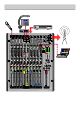
SERVICE OPTIONS
AUX Pre ON switch / Pre fade option (Mono, Telco and stereo
channels)
This is a cut and solder link that sets the acti on of the AUX pre
switch when it is in the down position.
The default setting is prefade which sources the audio signal after
the ON switch but before the channel fader. The option whe n mod-
ified sources the signal pre ON switch and post EQ.
Audition fader start option
(Mono and telco channels only)
Cut and solder link. The default for this option is to disable the
channel fader start signal if the audition bus button is depressed. If
the fader start option is required with the audition bus then cut and
re-solder this link.
Stereo channel input option
(channels ST1 - 3 only)
This option enables the stereo sources for these channels to be
mixed and fed into the channe l toget her. Simply move the position
of all 4 jumpers to their opposing position to enable this option.
The red gain pots can still be used to set r elative levels. The green
selection LEDs will both stay on to indicate that both channels are
being mixed. The main channel fader now contro ls both inputs.
Program fader bypass
(Mix PCB)
By moving the position of t hese 2 jumpers, the main program fader
will be bypassed. This elimi nates the possibility of the program fader
being accidentally pulled down.
CRM / Guest additive mix option
(Master & meter PCBs)
By bridging all eight solder links on the mast er and meter PCBs re-
spectively, the feed selec tion buttons on the right hand side of the
mixer are changed from priority m ix t o additive mix. The default
setting is priority mixi ng wh ere pressing a button higher up on the
mixer cuts the previo us signal to listen to th e selected signal.
In additive mixing mode th e b o ttom button still priority switches
between the main program mix and Mix B but all other feeds are
mixed in to the signal when pressed.
Mix B / Rec out solder option
(Distribution PCB)
Cut and solder link. Cutt ing and re-soldering these 2 links changes
the Mix B out phono sockets to provide a pre fader program mix
for recording purposes.
Comms mic mix option
(Logic PCB)
Cutting or adding wire links here determines the source of the mi-
crophone signal tha t is used to talk to telephone callers and studio
guests with the mixer talk bu ttons. The signal is sourced after the
channel gain pot and so is not affect ed by the channel faders. A sin-
gle source or a mix of sources can be used. The default is M1.
Mic fader mute option
(Logic PCB)
Cutting or adding wire links here selects whi ch microphone chan-
nels will mute the co ntrol room speakers when a channel fader is
raised and the corresponding ON switch depressed. The default is
that all mic channels will m ute the control room feed but any com-
bination can be used.
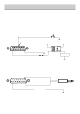
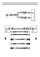
C UT TR AC K
HERE
SO LDER BLO B
HERE
Cut and solder option
NOTE: when cutting
track ensure cut lines
don't extend beyond
marked area
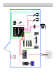
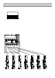
JP4
JP1
JP2
JP3
Stereo channel jumpers
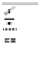
PGM FADER
BYPASS
JP8
JP7
CN17
CN16
Additive mix options
Add a solder bridge to each pair of pads
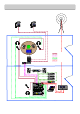
MUTE
FADERMIC
MIX
MIC
COMMS
M1 M2 M3 M4 M1 M2 M3 M4