
User Manual

Allen & Heath 28 XB-14 MK2 User Guide
ON ON ON ON ON ON ON ON ON ON ON ON
DISAB LE ON SWITCHES
MONO IN PUTS
1234
(MA KE PERMANENTLY O N)
T1 T2 1 2 3 4
STEREO INPUTS
LEDs FOLLOW SWITCH
DISA BLE STEREO
MUTE CIRCUIT (JAM ON)
BUT
(LED'S ALWAYS ON)
ON ALL 4 S TEREO C Hs
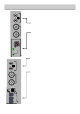
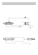
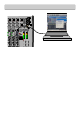
REMOTE INTERFACE CONNECTORS
External Meter socket
This can be used to feed the mai n Program PGM L & R signals to external metering equipment. These are line level
analogue signals, the level at 0VU wil l be 0dBu.
+/- 15V power is also available to power meter circuits, current draw should be kept under 100mA or so.
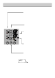
9 Way D socket connector EXTERNAL METER
PIN FUNCTION
1 +15V POWER
2 -15V POWER
3 GROUND
4 LEFT METER
5 RIGHT METER
6 GROUND
7 GROUND
8 GROUND
9 +10V POWER
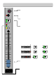
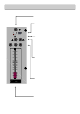
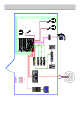
Configuration Switches
The tiny slide switches accessible on the rear panel are for configuring the XB-14’s channel ON switches. In t he u p position,
the channel ON switch will ac t as a normal ON/OFF switch affecting the channel signal accordingly. If the slide switch is moved
down to the “ON” position, then the corresponding channel’s ON switch will be disabled (made so that it is jammed ON).
The green LEDs in the switch will then permanently illuminate. UNLESS….
Unless you are using the Stereo channel O N switches for transport Start/Cue and would like the channel mute circuit disabled
but the switch illumi nat ion still to follow the switch position. In this case use the las t switch in the row to disable the mute
circuit on all 4 stereo chann e l s, but make the illumi nation follow the switch position.
If you want, you can disable the Stereo chan nel mute circuit on an individual channel basis using the Stereo Inputs 1,2 ,3 & 4
slide switches individually. This will make the channel permanently on and the switch illumination also permanently on.
This may seem like a fussy complication, but could be useful if you want to revert to basic operation, where only the faders
control the signal going out on air, disabling the O N switches so the operator cannot turn off the channel accidentally, but still
want the switch illuminat ion on certain stereo channels to follow the Start/Cue on the CD player or deck.
ALSO SEE P22 FOR A DIAGRAM TO EXPLAIN THESE SETTINGS.
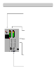
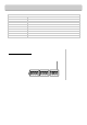
ON SWITCH OPTIONS
STANDARD OPERATION
OPTIONAL OPERATION