
User Manual


Allen & Heath 18 XB-14 MK2 User Guide
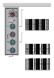
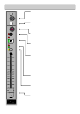
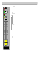
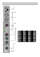
TELCO CHANNELS
TELCO Input Gain
The Telephone Communication channel input gain control. Varies
the gain applied to the T ELCO input channel from –10dB to +26dB.
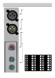
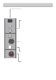
TEL IN
The Telephone Communication channel in put XLR socket. Wired
as Pin 1=Chassis, Pin 2=hot (+), Pin 3=Cold (-).
CLF OUT
Standard XLR output connector for the Clean-Feed output from
the Telephone Communication channel.
Wired Pin 1=Chassis, Pin 2=hot (+), Pin 3=Cold (impedance bal-
anced ground).
TELCO Channel Filters
The TELCO Channel has a hi gh pass and low pass total cut filter which
is designed to allow the user to reduce the frequency range of the
channel when used with a telephone caller.
The high pass filter can be varied from 20Hz (full range) to 6kHz. The
low pass filter from 20kHz (ful l range) to 700Hz.
The default position (full range frequency response) is shown.
20.0 0 Hz 100.00 1000.00 10000.00 30000.00
-30.00
-25.00
-20.00
-15.00
-10.00
-5.00
0.00
5.00
dBr
CLF OUT
TELC O 1
TEL IN
-1O
26
-5
5
10
20
0
GAI N
T1
700Hz 20k
3k
LPF
HPF
20Hz 6kHz
120Hz