- - - - SCEPTER 12 channel - Rack Mount Mixer -.
ALLEN & HEATH - - This product continues ALLEN & HEATH’s commitment to provide high quality tools engineered to meet the exacting requirements of today’s audio business. It brings you the latest in high performance technology and offers the reassurance of over two decades of audio console manufacture and customer support. _ _-- Whilst we believe the information in this manual to be correct and reliable we do not assume responsibility for any errors or omissions.
- - - - - -- - - ALLEN & HEATH BRENELL LTD. LIMITED ONE YEAR WARRANTY This product has been manufactured in the UK by ALLEN & HEATH BRENELL LTD and is warranted to be free from defects in materials or workmanship for a period of one year from the date of purchase by the original owner. To ensure proper validation and handling of warranty services please return the WARRANTY REGISTRATION CARD,.
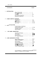
Allen & Heath PAGE CONTENTS 1 ...... INTRODUCTION General Information. ......................... ................ 1 Safety & Precaution .......................................... 2 installation ........................................................ 3-4 User Service Information ................................... 5 Electronic Performance ..................................... 6-7 2 ...... PANEL CONTROL DIAGRAMS Input Channels ................................................. 8-9 L/R Section ............
Allen & Heath CONTENTS continued - PAGE 6 . . . . . . SERVICE INFORMATION DIAGRAMS Main IDC Ribbon Connector . . . . . . . . . ...* ..*...,......... Dimensions Diagram . . . . . . . . . ..*......*...... ..*.....*.*..*.. System Block Diagram .,..*.*..*.....*..,... . . . . . . . ...*..... 7...... SCHEMATIC DIAGRAMS -_ ... - Input Components and Option Placement.. ....... Input Circuit Diagram ........................ ................
Section 1 Audio Owner Manual INTRODUCTION - The Allen & Heath SCEPTER RACK MOUNT MIXER is a versatile, economical and easy-to-use general purpose rack mount mixer intended for stereo and mono PA applications as well as stereo recording. The quality of design, construction and components employed will ensure high performance in these applications when correctly used. Operators and installers are encouraged to study the contents of this handbook. - Construction: - 1. 2. 3. 4. 5. 6. 7.
Section 1 Audio Owner Manual Mains electricity is dangerous and can kill. Mains voltage is present within the power unit but not the Scepter unit. Check your mains wiring and earthing before connecting up and switching on. The purpose of the “earth” (ground) connection in a mains supply is for the prevention of electric shock from the mains voltage present. It is usual for the chassis of mains powered equipment to be connected to earth to prevent the metal parts becoming “live” and causing electric shock.
Section 1 Audio Owner Manual - INSTALLATION - .- - Unpack the unit from the packing carton. Remove the power supply unit from the packing. We recommend that you keep intact this purpose designed packing to reuse should you need to ship the unit in the future. Please ensure that the Scepter unit, power supply and other items are correctly repacked to avoid transit damage. Please ensure that the fader knobs are in the up position.
Section 1 Audio Owner Manual The console is not connected to mains earth for the reasons mentioned above and under normal operating conditions it contains no dangerous voltages. The power supply chassis is connected to mains earth and must never be disconnected. Likewise never disconnect the earth wire in the mains plug. It is best to plan ahead and have your installation checked by a competent engineer before you commence. Do not trust equipment and installations modified by others.
Section 1 Audio Owner Manual - - USER SERVICE INFORMATION .- There are no adjustments or alignment procedures required to maintain the performance standards of this Allen & Heath product. To preserve the working life of the unit and its presentation, avoid the use of chemicals, abrasives and solvents. The control panel is best cleaned with a soft brush and a damp cloth. Switches and potentiometers are lubricated for life; the application of electrical lubricants to these parts is not recommended.
Section 1 Audio Owner Manual ELECTRONIC PERFORMANCE OdBu - 0.776 Volts RMS 1 kHz OVU = +4dBu = 1.23 Volts RMS Unreferenced dB represents Voltage Gain MAX VOLTAGE GAIN: Figures include 10dB input and group fader boost MIC IN to L/R Out,.., ,,,.........I*.........*. +80dB LINE IN to L/R Out . . . . . . . . ..*..........*....* +62dB L/R to Mono Out..,.,. .....**......*.......s.*. +1 OdB FX RETURN to L/R Out . . . . . . . . . . . . . . . . . . . . +24dB INPUT PAD ..a.....,.... ,,,......................
- +a Section 1 Audio Owner Manual - - -- ELECTRONIC PERFORMANCE continued THD typically better than 0.
Section 2 Audio Owner Manual FRONT PANEL CONTROLS. INPUT CHANNEL 1. LINE L-J GAIN Adjusts the gain of the input pre-amplifier to suit input levels. Control range is +18 to +66dB (mic) and -4 to +43dB (line). PAD 2. - LINE Selects between Microphone and Line input sources. With the switch engaged, Line input is selected. 3. PAD When selected, reduces the input signal level by approximately 16dB. 4.
- Section 2 Audio Owner Manual - FRONT PANEL CONTROLS - INPUT CHANNEL (cant) - - 11. HIGH PASS FILTER SWITCH Causes a gradual roll off in level of all frequencies below 80Hz at a rate of -12dB per octave. Useful in eliminating unwanted low frequency sounds. - 12. - Positions input signal anywhere between the Left and Right outputs of the stereo mix. Full counter-clockwise routes all of the input signal to the left channel. Full clockwise routes all of the input signal to the right channel.
Audio Owner Manual Section 2 FRONT PANEL CONTROLS MONITOR L LEFT/RIGHT SECTION (Left is Shown) +6 References in ( ) are for Right Master +3 -0 1. -3 L(R) MONITOR METERS These multipurpose meters monitor any source selected by the Monitor section of the Master Module. When no switch is selected within the monitor section, Left and Right outputs are displayed. When any PFL switch on the mixer is engaged, these meters automatically display the signal that is present at that position.
Section 2 Audio Owner Manual - FRONT PANEL CONTROLS - L/R CHANNEL (Cont) - LEFT/RIGHT SECTION Left is Shown References in ( ) are for Right Master - 3. The two STEREO RETURN inputs allow STEREO input signals (i.e. the output of stereo tape machines or stereo effects devices) to be mixed with the main outputs. The l/4” TRS(stereo) jack accepts -10 levels; Left on Tip, Right on Ring.
Section 2 Audio Owner Manual FRONT PANEL CONTROLS - MASTER SECTION 12v LAMP 1. 12V LAMP BNC Connector to accept most of the popular goose neck lamps to illuminate the mixer work area. B 1-j +48 2. D PWRON Master power switch for 48 Volt PHANTOM POWER (for use with CONDENSER microphones). A 3. B +46 PHANTOM POWER LED Indicates that the Master Phantom Power switch is turned on and phantom power is present in the mixer. 4 5 6 4. POWER ON LED Indicates that power is on to the mixer.
- Audio Owner Manual Section 2 FRONT PANEL CONTROLS - MASTER SECTION (cant) AUX A 0 - a. AUX B AUX C AUX D - 1-1 MONO I - MONITOR SELECT and LEVEL This section selects the signal to the HEADPHONE OUTPUT on the front panel and the MONITOR OUTPUT on the rear panel. It also routes the selected signal to the LED Meter section of the mixer. If no switches are engaged (and no PFL LED illuminated), this signal is the LEFT/RIGHT output of the console.
Section 2 Audio Owner Manual MASTER 0 PIN 1 LIFT 0, MASTER CONNECTIONS PIN 1 LIFT Used to disconnect pin 1 from the MONO output connector. Used to eliminate ground loops. MONO BAL OUT Male XLR-3 (Pin 2 Hot). Self Compensating Electronically Balanced. Controlled by Mono Out Level pot. Normally derived from mix of Pre-Fader Left & Right(See Options Section). Nom level of +4dBv; Capable of +27dBv output into 600 ohms or greater. AUX OUT A 0 AUX OUT B 0 AUX OUT C AUXAUNBALANCEDOUT l/4” Jack.
Section 2 Audio Owner Manual - LEFT & (RIGHT) CONNECTIONS LEFT PIN 1 LIFT - Used to disconnect pin 1 from the LEFT(RIGHT) output connector. Use to eliminate ground loops. - LEFT(RIGHT) BAL OUT Male XLR3 (Pin 2 Hot). Seff Compensating Electronically Balanced. Capable of +27dBv output into 600 ohms or greater. _ EFX RETURN 1 (2) INPUT l/4” Stereo Jack Tip accepts -10 devices, Ring accepts +4 devices EFX RTN EFX RETURN 3 (4) INPUT l/4” Stereo Jack.
Section 2 Audio Owner Manual INPUT INPUT CHANNELS INDIVIDUAL PHANTOM POWER SWITCH When engaged, turns on the +48v phantom power for that channel if the Master +43v switch on Front Panel is on. MIC INPUT CONNECTOR 3-pin Female XLR connector used to connect balanced low (mic) level signals into the channel. LINE INPUT JACK Balanced l/4” stereo jack used to connect high (line) level signals into the channel. Will accept balanced or unbalanced signals.
- Section 3 Audio Owner Manual - - - - - USING THE SCEPTER SERIES MIXER THE INPUT CHANNEL The input channel accepts a balanced or unbalanced input signal from a microphone, direct box or a line level source such as the output of a synthesizer, or external signal processing device such as a digital delay line, reverb, etc. Phantom Power 1 The SCEPTER Series Mixers are factory wired for the +48 volt DC. phantom powering of condenser microphones.
Section 3 Audio Owner Manual Channel Auxlliary Sends Each Scepter input channel features four auxiliary send controls. These controls feed auxiliary masters A, B, C and D and allow the user to create four additional mixes of the signal sources fed to the mixer. These mixes are generally used as feeds to external FX devices, as foldback mixes to an onstage monitor system, or as a cue mix for performers headphones in recording situations. Aux A and B are normally PRE-EQ feeds to the Aux A and B mixes.
Section 3 Audio Owner Manual Mid Frequency Equalizer This control provides 12dB of boost or cut at the frequency selected by the Mid Select control. This is a peak/dip type equalizer. It affects sounds both above and below the selected frequency within a range of approximately one octave (Q-l .4). This means that boosting the mid equalizer at 2k affects not only 2k but also the frequencies surrounding it, but to a lesser degree.
Section 3 Audio Owner Manual PFL Button (Pm-Fader Llsten) Engaging the PFL allows you to listen to the Pre-Fader signal in the monitor and headphone outputs. The PFL system takes its signal after the EQ section but before the channel fader. This allows you to make signal level and quality checks before bringing up the channel in the mix.
Section 3 Audio Owner Manual LEFT/RIGHT SECTION L/R Monitor Meters Each meter is a IO segment LED display which provide a visual indication of the source selected by the monitor select switches. Calibrated in 3dB steps from -21dB to +6dB, each meter is a VU type(average) responding meter with the 0 position indicating an output level of +4dBu (1.23~ RMS).
Section 3 Audio Owner Manual MASTER SECTION 12V Lamp This BNC Connector will accept 12 volt D.C. goose neck lamps rated at 50mA to 150mA current consumption. Used to illuminate the mixer work area. +48 Master power switch for +48 Volt PHANTOM POWER (for use with CONDENSER microphones). When this switch is depressed, the LED will illuminate indicating that power is supplied to any channel whose individual Phantom switch is on. Power on LED Indicates that power is being supplied to the mixer.
Section 3 Audio Owner Manual I- h h.. Monitor Select and Level This section selects the signal for the HEADPHONE OUTPUT on the front panel and the MONITOR OUTPUT on the rear panel. It also routes the selected signal to the LED Meters. If no switches are selected (and no PFL LED illuminated), this signal is the LEFT/RIGHT output of the console. When a monitor select switch is depressed, it routes the selected signal to the Meters, Headphones and Monitor Output.
Section 4 Audio Owner Manual REAR PANEL CONNECTORS INPUT CHANNEL CONNECTIONS Individual Phantom Power Switch When selected, this switches the +48v D.C. phantom power for that channel but only if the Master +48 switch is also selected on the front panel. Use this switch only for condenser mics that need powering. Avoid using phantom power on dynamic or ribbon mics. A dynamic mic will usually be unaffected, but damage can occur to some ribbons.
Section 4 Audio Owner Manual LEFT & RIGHT CHANNEL CONNECTIONS Pin 1 Lift This recessed switch is used to disconnect Pin 1 from ground on the LEFT/ RIGHT output XLR connectors. Used to eliminate ground loops when connecting up different pieces of equipment Use a pencil or other thin probe to activate the switch; Pin 1 is lifted when the switch is IN. ,- L - - -- Left/Right Main Outputs Main outputs for the Left and Right mix amps. These XLR connector outputs follow the L/R faders.
Section 4 Audio Owner Manual greater. The return impedance is 10k Ohm. L/R Bus In This l/4” unbalanced jack is used to inject signals into the Left & Right mix amps. Use this jack when stacking 2 mixers together. This allows the Slave mixer outputs to get to the Master mixer without tying up input channels or returns. The nominal level is -2dBu with an input impedance of 33k Ohm.
Section 4 Audio Owner Manual - MASTER SECTION CONNECTIONS Pin 1 Lift - This recessed switch is used to disconnect Pin 1 from ground on the MONO output XLR connector. Used to eliminate ground loops when connecting up different pieces of equipment Use a pencil or other thin probe to activate the switch; Pin 1 is lifted when the switch is IN. Mono Output Main Mono output. Normal source is a mix of L&R Pre-insert signals. User may select; either Post-insert L&R or Post-fader L&R.
Section 4 Audio Owner Manual jack to feed a mix to a Control room amp in a studio situation, or a performer mix for a keyboard player. Output level is variable, max output is +2ldBu into 600 Ohm or greater. Tip is Left, Ring is right. The Headphone jack on the front panel follows the same signal as this output but is designed to drive a pair of headphones (75 Ohm or greater).
Section 4 Audio Owner Manual DC POWER CONNECTOR - - 5Pin male XLR for connection to Allen & Heath power supply unit. MPS-8R is normally supplied with the Scepter, but an MPS-8P, MPS-9, or RPS-1 with the proper cable can also be used. Your warranty will be void if a power supply not supplied or approved by Allen & Heath is used. The Scepter is designed to allow. the user to lift the chassis from the audio ground.
Section 5 Audio Owner Manual SERVICE ACCESS ACCESS TO MIXER CIRCUITS To implement any User Options, you will need to gain access to the internal circuit cards, The various jumper links later defined are located on those cards. Follow the outlined procedure to safely open the Scepter mixer. The Scepter is composed of individual glass-epoxy circuit cards secured to a silk-screened aluminum front panel. A steel rear panel is secured to the rear of the circuit cards by numerous jack nuts.
Section 5 Audio Owner Manual - a - -- 9 10 11 to be carried out. Free the DC power XLR-5 pin insert from its metal shell by using a small screwdriver to loosen the XLR setscrew (anti-clockwise). The insert can then be pulled out the back of the XLR shell. The DC wires to the Master card will remain attached to the insert. Remove the loosened plastic nuts from the l/4” jacks. Remove the 2 fixing screws from each XLR jack. Lift the Rear panel off the circuit cards.
Section 5 Audio Owner Manual USER CONFIGURED OPTIONS There are a number of User options available on the Scepter mixer. They are implemented with removable jumper links that the user can move to different combinations of header pins; no soldering is necessary. (except for the left and right Stereo Return options). To alter any of the User Configured Options you will have to gain access to the internal circuit cards. Please read the ACCESS TO MIXER CIRCUITS procedure in the SERVICE ACCESS section.
Section 5 Audio Owner Manual - - -.- Channel Aux Send Source Select Three choices are available for each of the four Auxiliary Sends. Aux A & B are set up as Monitor or Cue sends (Pre-EQ/Pre-Fader); Aux C & D are set as EFX sends (Post-Fader). Normally all Aux sends are muted along with the channel, but the Pre-EQ source can be set to ignore the Mute switch. (see Pre-Eq Mute/No mute section) The Pre-EQ can also be set to 1 of 3 different configurations (See Pre-EQ Source Select).
Section 5 Audio Owner Manual PreEQ Mute/No Mute The Pre-EQ source (1 of 3 selected above) can be set to follow the Channel Mute switch or to ignore it. It is normally set to follow the mute. If you desire the source to be active even when the channel is muted, configure the No Mute option. 1 Pre-EQ Mute Pre-EQ source will mute with the Channel. This is the factory default setting. 2 Pre-EQ No Mute Pre-EQ source will remain on even when the channel is muted.
Audio Owner Manual Section 5 Master Options The user can choose the sources for both the Balanced MONO out XLR connector and the STEREO OUT l/4” jack socket. These outputs are derived from some point in the main Left and Right audio path. The options are: Pre-Insert, PostInsert/Pre-Fader and Post-Fader. Normally both the Mono and Stereo outputs are set for Pre-Insert. This makes them independent of the main L & R faders and any processing equipment that is patched into the Left or Right Insert jacks.
Section 5 Audio Owner Manual brought out to holes in the circuit board allowing you to feed an Aux output or other signal to the Stereo Out. Solder a wire between the hole pad and the desired signal point and move the header to the Ext position. OPTIONS TABLE All the possible Scepter user options are listed in the table below with the factory defaults indicated with an X. Diagrams on the following pages show the Scepter circuit cards and where the various jumper links and default jumpers are located.
Section 5 Audio Owner Manual - CHASSIS GROUND LIFT - - Normally the chassis of the Scepter is connected to the audio ground with a link on the DC Input connector. The chassis can be lifted from the audio ground by removing this link. This should not be confused with disconnecting the ground on an AC plug. The AC ground is a safety ground; it is there as protection from electrocution if some component should fail and cause an exposed surface to become live.