ALLEN&HEATH WARNING – HIGH VOLTAGES Power Supply Unit (PSU) work should only be carried out by qualified personnel. We recommend that you use an approved Allen & Heath service centre for all power supply work. Please contact your local Allen & Heath distributor for more details. http://www.allen-heath.
Section 5 Audio Owner Manual SERVICE ACCESS ACCESS TO MIXER CIRCUITS To implement any User Options, you will need to gain access to the internal circuit cards, The various jumper links later defined are located on those cards. Follow the outlined procedure to safely open the Scepter mixer. The Scepter is composed of individual glass-epoxy circuit cards secured to a silk-screened aluminum front panel. A steel rear panel is secured to the rear of the circuit cards by numerous jack nuts.
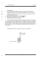
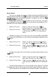
Section 5 Audio Owner Manual - a - -- 9 10 11 to be carried out. Free the DC power XLR-5 pin insert from its metal shell by using a small screwdriver to loosen the XLR setscrew (anti-clockwise). The insert can then be pulled out the back of the XLR shell. The DC wires to the Master card will remain attached to the insert. Remove the loosened plastic nuts from the l/4” jacks. Remove the 2 fixing screws from each XLR jack. Lift the Rear panel off the circuit cards.
Section 5 Audio Owner Manual USER CONFIGURED OPTIONS There are a number of User options available on the Scepter mixer. They are implemented with removable jumper links that the user can move to different combinations of header pins; no soldering is necessary. (except for the left and right Stereo Return options). To alter any of the User Configured Options you will have to gain access to the internal circuit cards. Please read the ACCESS TO MIXER CIRCUITS procedure in the SERVICE ACCESS section.
Section 5 Audio Owner Manual - - -.- Channel Aux Send Source Select Three choices are available for each of the four Auxiliary Sends. Aux A & B are set up as Monitor or Cue sends (Pre-EQ/Pre-Fader); Aux C & D are set as EFX sends (Post-Fader). Normally all Aux sends are muted along with the channel, but the Pre-EQ source can be set to ignore the Mute switch. (see Pre-Eq Mute/No mute section) The Pre-EQ can also be set to 1 of 3 different configurations (See Pre-EQ Source Select).
Section 5 Audio Owner Manual PreEQ Mute/No Mute The Pre-EQ source (1 of 3 selected above) can be set to follow the Channel Mute switch or to ignore it. It is normally set to follow the mute. If you desire the source to be active even when the channel is muted, configure the No Mute option. 1 Pre-EQ Mute Pre-EQ source will mute with the Channel. This is the factory default setting. 2 Pre-EQ No Mute Pre-EQ source will remain on even when the channel is muted.
Audio Owner Manual Section 5 Master Options The user can choose the sources for both the Balanced MONO out XLR connector and the STEREO OUT l/4” jack socket. These outputs are derived from some point in the main Left and Right audio path. The options are: Pre-Insert, PostInsert/Pre-Fader and Post-Fader. Normally both the Mono and Stereo outputs are set for Pre-Insert. This makes them independent of the main L & R faders and any processing equipment that is patched into the Left or Right Insert jacks.
Section 5 Audio Owner Manual brought out to holes in the circuit board allowing you to feed an Aux output or other signal to the Stereo Out. Solder a wire between the hole pad and the desired signal point and move the header to the Ext position. OPTIONS TABLE All the possible Scepter user options are listed in the table below with the factory defaults indicated with an X. Diagrams on the following pages show the Scepter circuit cards and where the various jumper links and default jumpers are located.
Section 5 Audio Owner Manual - CHASSIS GROUND LIFT - - Normally the chassis of the Scepter is connected to the audio ground with a link on the DC Input connector. The chassis can be lifted from the audio ground by removing this link. This should not be confused with disconnecting the ground on an AC plug. The AC ground is a safety ground; it is there as protection from electrocution if some component should fail and cause an exposed surface to become live.
Audio Owner Manual - - - Section 6 SERVICE INFORMATION AND DIAGRAMS
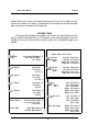
h/iAIN RIBBON SIGNALS TOP VIEW 19 1 20 2 u u u u u u u u u u VIEW ON PINS h,IAIN RIBBON SIGNALS J 17 AUDIO +15 VOLTS 19 AUDIO -15 VOLTS 18 LED +15 VOLTS 20 LED -15 VOLTS NOTE: The Silkscreen legends on the PCBs are in error (odds and evens are reversed). locations are correct as sho&m above.
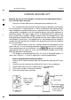
SCEPTER R A CK MIXER - 10 RACK SPACES DEPTH BEHIND PANEL 1 19 (483) PANEL (94) HEIGHT ABOVE 1 .4 (36) PANEL (HANDLES) 1 .