ALLEN&HEATH WARNING – HIGH VOLTAGES Power Supply Unit (PSU) work should only be carried out by qualified personnel. We recommend that you use an approved Allen & Heath service centre for all power supply work. Please contact your local Allen & Heath distributor for more details. http://www.allen-heath.
ALLEN&HEATH ML5000 Dual Function Live Sound Console SERVICE MANUAL Publication AP3737
Introduction This service manual provides technical information on the Allen & Heath ML5000 audio console. Included is the technical specification, system block diagram, circuit schematics with board layouts, and a spare parts list. Information on the power supply is available in a separate publication. Only technically qualified service personnel should carry out service work on the console and its power supply.
Contents Important Safety Instructions ............................ 4 Mains Plug Wiring Instructions ......................... 5 General Precautions ......................................... 5 ML5000 Key Features ...................................... 6 Front Panel Layout............................................ 7 Rear Panel Layout ............................................ 8 Functional Description ...................................... 9 Installing the Console......................................
Important Safety Instructions WARNINGS - Read the following before proceeding : CAUTION ATTENTION: RISQUE DE CHOC ELECTRIQUE – NE PAS OUVRIR Read instructions: Retain these safety and operating instructions for future reference. Adhere to all warnings printed here and on the console power unit. Follow the operating instructions printed in the user guide and the power unit user guide. Do not remove covers: Operate the power unit with its covers correctly fitted.
Important Mains Plug Wiring Instructions. The power unit is supplied with a moulded mains plug fitted to the AC mains power lead. Follow the instructions below if the mains plug has to be replaced.
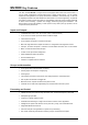
ML5000 Key Features The Allen & Heath ML5000 is a large format VCA equipped dual function live sound console. It can be quickly configured for front-of-house (FOH) or stage monitor mixing. As one console suitable for both applications it is equally well suited to installation, rental and touring.
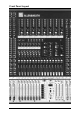
Front Panel Layout ML5000 Service Manual 7
Rear Panel Layout 8 ML5000 Service Manual
MONO INPUT and EQ. The input preamp matches microphone or line level signals to the console. The sweepable high pass filter removes unwanted low frequency sounds below the selected frequency. The channel insert is post filter, pre EQ. A swept frequency 4 band equaliser provides shelving high and low bands with adjustable shelf frequency, and fully parametric high and low mid bands with adjustable centre frequency and Q. The filter and EQ can be independently switched in or out. GRP/AUX SENDS.
Installing the Console Weights 32 Channel 40 Channel 48 Channel 24 Channel sidecar MPS14 psu 84 kg (185 lbs) 96 kg (211 lbs) 110 kg (242 lbs) 45 kg (95 lbs) 6 kg (13 lbs) HEADPHONES SOCKETS UNDER ARMREST LAMP SOCKETS 298 130 872 ML5000-24SC = 831 ML5000-32 = 1596 ML5000-40 = 1851 ML5000-48 = 2106 440 482.6 FC 76.2 90 263 REMOVABLE RACK EARS 2U HEIGHT Refer to the power supply user guide for safety and installation instructions. Heed all warnings printed in the user guide and on the power unit.
The Expander Sidecar The Allen & Heath ML5000-24SC Sidecar is the 24 mono input channel expander for the ML5000 console. It is free standing and does not need to be mechanically fixed to the main console. Interconnection is by means of multiway cables to link the audio signals and control logic. It is supplied with its own power supply unit independent of the console. The input channel strip is identical to the main console with all functions available.
Diagram 1 +48V 20 PAD 40 20dB GAIN - 10 10 OUTPUT INPUT 2 1 INPUT OUTPUT O 60 40 100 50 200 30 HPF 400 20Hz 7kHz 3k 10k 2kHz 20kHz - 15 +15 1.2 HF Q CONNECTING ONE SIDECAR Diagram 2 0.6 2.5 2kHz 1k 3k 500 5k 400Hz 20kHz HM MAIN CONSOLE - 15 +15 1.2 Q ML5000 0.6 2.
Combining Sidecar Power Supplies for Backup If you are connecting two sidecars then you can link the power supplies together for redundant supply backup. One MPS14 supply is capable of running both sidecars together should the other fail. You need to order the short 0.7 meter DC power cable (part 002-584) for linking. Note: Do not link the main console power supply to the sidecar supply in this way. One supply is not capable of running both the main console and its sidecar should the other fail.
The MPS14 Power Supply The slimline MPS14 power supply uses linear post-regulated switch mode technology to generate the DC voltages required by the console. It will operate from a wide range of ac mains input voltages. Full protection and thermally controlled fan cooling ensures the power unit will operate consistently. The MPS14 also has a built in combiner for connection to a second supply for backup.
MPS14 Technical specifications Mains Input Voltage Range 100 - 240 ± 10% VAC @ 47-63 Hz auto-sensing Power consumption (max.) 500W Mains Fuse: 100 - 240 V~ T 5.0A/250V PCB Ident F1 (+12V) F2 (+48V) F18 (aux psu) Fuse type T 6.3A 250V 20mm T 2A 250V 20mm T 500mA 250V 20mm Internal Fuses: ML5000 DIRECT OUT DIRECT OUT DIRECT OUT INSERT SEND INSERT SEND INSERT SEND RET RET RET IN DC Outputs DC Voltage Rail +17 VOLTS -17 VOLTS +12 VOLTS +48 VOLTS MPS14 Output Current 7A Max. 7A Max. 5A Max.
ML5000 Technical Specifications 0dBu = 0.775 Vrms, +4dBu = 1.23 Vrms Operating Levels Channels ......................................... 0dBu Headroom +21dB Mix .................................................. -2dBu Headroom +23dB Frequency Response Referred to 1kHz at +4dBu Mic to main output (+40dB)............. 20Hz to 30kHz +0/-0.5dB Line to main output (0dB)................ 20Hz to 30kHz +0/-0.5dB Distortion @1kHz +14dBu THD+noise ...................................... < 0.
System Block Diagram (1 of 2) VCA GROUPS METER PFL MUTE PEAK L MUTE GROUPS SNAPSHOTS GAIN +48V C R PAD INSERT SEND RETURN HPF IN + - PAFL PAFL LOGIC FADER MONO CHANNEL VCA EQ IN + - PAN LCR+ + L AFL + R AFL MAIN MIX BLEND L MIX R MIX C MIX INPUT FILTER FREQ L 4 BAND EQUALISER LF LM HM R LR C HF PRE-FADE AUX OPTION LINKS POST-MUTE J7 J3 PRE-EQ J2 PRE-INSERT J1 GRP PAN ON J8 POST-EQ MONO STEREO PRE-FADE POST-FADE ODD GRP EVEN DIRECT OUT OPTION LINKS PRE PRE
System Block Diagram (2 of 2) GRP/AUX 1-16 AFL AFL LOGIC TB ENABLE METER TB PEAK EXT IN MUTE INSERT SEND RETURN MIX GRP AUX MUTE GROUPS SNAPSHOTS MAIN MIX BLEND PAN + - LCR+ L SET mode FOR EITHER: R LR R AFL + - L MIX R MIX C MIX GRP/AUX1 (1-8 ONLY) C GRP/AUX 2 GROUP = SWITCHED ROUTING AUX = VARIABLE LEVEL+PRE/POST SWITCH GRP/AUX 3 GRP/AUX AFL AFL LOGIC GRP/AUX 4 GRP/AUX OUT BAL POST AUX 1-8 GRP/AUX 5 GRP/AUX 6 L AFL MIX MATRIX L AFL FADER mode MASTER POST AUX OUT
Connector Types and Wiring ML5000 Service Manual 19
Gain Structure (Reprinted from User Guide) Matching the Console to Destination Equipment. The console produces a standard XLR output level of 0dBu for a meter reading of ‘0’ and +22dBu maximum to allow plenty of headroom for driving equipment hotter. If you are connecting directly to a sensitive power amplifier it is advisable to turn down its input trim control if the normal console level is too high.
Channel Jumper Options 2-TRACK Jumper Options Several link options are available to satisfy user preferences. These require removal of the console base panels and replugging of 2way jumpers on the circuit boards. It is not necessary to remove assemblies from the console. To avoid damage to the internal assemblies this work should be carried out by competent technical personnel. The 2-track output is sourced from the main LR mix. The factory default setting is post master LR faders.
MIDI Mutes HEX 00 01 02 03 04 05 06 07 08 09 0A 0B 0C 0D 0E 0F 10 11 12 13 14 15 16 17 HEX 20 21 22 23 24 25 26 27 28 29 2A 2B 2C 2D 2E 2F 30 31 32 33 34 35 36 37 MUTE GRP/AUX 1 GRP/AUX 2 GRP/AUX 3 GRP/AUX 4 GRP/AUX 5 GRP/AUX 6 GRP/AUX 7 GRP/AUX 8 AUX 9 AUX 10 AUX 11 AUX 12 AUX 13 AUX 14 AUX 15 AUX 16 MATRIX 1 MATRIX 2 MATRIX 3 MATRIX 4 MATRIX 5 MATRIX 6 MATRIX 7 MATRIX 8 MUTE CH 1 CH 2 CH 3 CH 4 CH 5 CH 6 CH 7 CH 8 CH 9 CH 10 CH 11 CH 12 CH 13 CH 14 CH 15 CH 16 CH 17 CH 18 CH 19 CH 20 CH 21 CH 22 CH 23
Archiving the Console Settings MIDI Dump Message Format The console settings can be saved to an external device such as a MIDI sequencer or data archiver using the dump out facility. Saved settings can be loaded back into the console using dump in. This is ideal when you want to archive the settings to use at a later date, for example a re-run of a previous performance.
Operating Software Technical Support Operating Software Version Number Power Up and Power Down The version number is briefly shown on the snapshot display on power up. Make sure the system amplifiers are muted or turned off before switching the console on or off. This example displays version 1.20 The console settings are saved when power is removed. On power up these settings are restored.
Servicing the Input Fader assembly Before beginning any service work, remove all power to the unit and disconnect any signal cables where necessary. Ensure adequate lighting and use the correct tools. Remove the numbered Ident strip by placing a flat headed screwdriver under one end and prizing it upwards. Remove the Ident strip by ‘peeling’ it from one end of the console to the other.
4) Carefully remove the Fader Slave PCB from the Mono Fader PCBs by pulling it upwards from the fader boards. 5) Once removed, turn the Fader Slave PCB over (see fig.3) To remove a Mono Fader PCB, use a 5.5mm spanner to remove the relevant M3x4 Taptite Hex Headed Screws (E) that attach the Mono Fader PCBs to the Input Fader Bracket (see fig.3). To remove a fader remove the two relevant M3x5 Countersunk Pozi Screws with under-head pips (C) as shown in fig.1.
Servicing the Master Fader assembly Before beginning any service work, remove all power to the unit and disconnect any signal cables where necessary. Ensure adequate lighting and use the correct tools. Remove the numbered Ident strip by placing a flat headed screwdriver under one end and prizing it upwards. Remove the Ident strip by ‘peeling’ it from one end of the console to the other.
The Stereo Slave PCB must be removed before the following PCBs can be removed; Mono Fader, Master Fader Centre, Master Fader L/R & Control Panel. 1) Cut the 2x Cable ties attaching the Stereo Slave PCB onto the Mono Fader & Control Panel PCBs. 2) Carefully remove the Stereo Slave PCB by pulling it upwards. 3) Once removed, turn the Stereo Slave PCB over. 4) To remove a PCB, use a 5.5mm spanner to remove the relevant M3x4 Taptite Hex Headed Screws that attach the PCBs to the Master Fader bracket.
Base removal and Internal PCB assemblies Before beginning any service work, remove all power to the unit and disconnect any signal cables where necessary. Ensure adequate lighting and use the correct tools. Before you can access the internal PCB assemblies, invert the console and remove the screws securing the base in place. Carefully lift the base off.
Removing a Mono Input PCB assembly Before beginning any service work, remove all power to the unit and disconnect any signal cables where necessary. Ensure adequate lighting and use the correct tools. 1) Remove the screws attaching the relevant Earth Strip running the length of the Mono section (see fig.6, right hand section only shown) then lift away the Earth Strip. Earth Strip 50 way IDC wireform SYS-LINK II PCB fig.
Removing the Master Distribution PCB assembly To access the Group and Auxiliary PCB assemblies it may be necessary to remove the Master Distribution PCB. Before beginning any service work, remove all power to the unit and disconnect any signal cables where necessary. Ensure adequate lighting and use the correct tools. 1) Before removing the Master Distribution PCB assembly, the console base must first be removed.
Servicing the Meterbridge Assembly Before beginning any service work, remove all power to the unit. Ensure adequate lighting and use the correct tools. 1) Remove all the plastic snap-in rivets along the face of the meter panel with your fingernails or other non-abrasive tool. 2) With a person standing at either end of the console, each using a small, thin screwdriver, place the screwdriver through each of the endmost bottom rivet holes (see fig 8).
Servicing the MPS14 Power Supply Cleaning and Replacing the fan filters. At regular intervals, it is recommended that the foam fan filters are cleaned or replaced to ensure efficient operation of the power unit. Failure to do so may reduce the efficiency or even damage the power unit. To remove the fan filters, switch off and disconnect all power to the MPS14. Remove the rack ears and place to one side. Remove the cover fixing screws and cover and place to one side.
ORDERING A CONSOLE To order a new console please specify the model number and AC mains voltage for the Power Supply. MODEL DESCRIPTION ORDER CODE ML5000-32 32 Mono + 4 Stereo Input Channels ML5000-32 ML5000-40 40 Mono + 4 Stereo Input Channels ML5000-40 ML5000-48 48 Mono + 4 Stereo Input Channels ML5000-48 MPS14 Power Supply for ML5000 MPS14/* * - Specify the voltage and mains plug requirement for your area. ORDERING AN ACCESSORY To order an option please specify the model number required.
ORDERING AN ASSEMBLY The following assemblies for the ML5000 are supplied fully tested. Please quote the description and order code for the part required.
IDC connector harnesses: DESCRIPTION ORDER CODE 10 way GRAUX harness AL4029 10 way Input harness AL4028 10 way LRC to Fader harness AL4077 10 way MIDI harness AL4032 16 way GRAUX harness AL4030 20 way Master Connector harness AL4027 20 way Meter harness AL4021 26 way CPU Power harness AL4033 26 way LRC Connector harness AL4031 26 way Distribution harness AL4020 26 way Slave A harness AL4022 26 way Slave B harness AL4023 26 way Slave C harness AL4024 26 way Slave D harness AL4025
ORDERING AN ML5000 SPARES KIT It is recommended that the spares kit order code 002-533 is held and maintained by the service agent to enable in-field service repairs to the ML5000 independent of the ALLEN & HEATH factory. Commonly available items such as resistors, capacitors, tools and soldering equipment are not included. The contents of the kit are listed below and are supplied in a cabinet of drawers. Individual spare parts may be ordered.
Button 6x6mm Square White AJ3951 10 Button 6x6mm Square Light Grey AJ3952 5 Button 6x6mm Square Red AJ3953 10 Button 6x6mm Square Black AJ3954 5 Button 8mm Round Light Grey AJ3955 10 Fader Knob 11mm White+Black Line AJ8078 10 Fader Knob 11mm Red+Black Line AJ8079 10 Fader Knob 11mm Yellow+Black Line AJ8080 5 Fader Knob 11mm Blue+Black Line AJ8081 10 Button Illuminated White AJ8107 10 Faders, Potentiometers, Switches and connectors: Pot 10KC x 2 (103C 14mm wide) AI0150 3 Pot
IC CMOS 4053B AE0117 10 IC CMOS 4051B AE0118 1 IC NE5532 Op-Amp AE0221 10 IC 6N136 Opto-Isolator AE0222 1 IC TTL 74LSOO AE0243 1 IC Opto-Isolator 4N35 AE0266 2 IC 7805 Regulator AE0308 3 IC SSM2018P VCA AE0315 5 IC RS232 HIN202CP AE2742 1 IC CMOS 74HC165 AE2749 3 IC CMOS 74HC4094N AE2755 5 IC Comparator LM393N AE2818 5 Transistor BC556B PNP AE3001 5 Crystal 14MHz AE3007 1 LED Square Red AE3489 5 LED Square Green AE3490 10 LED Square Yellow AE3491 5 Transist
ORDERING AN MPS14 SPARES KIT It is recommended that the spares kit order code 002-632 is held and maintained by the service agent to enable in-field service repairs to the MPS14 independent of the ALLEN & HEATH factory. Commonly available items such as resistors, capacitors, tools and soldering equipment are not included. The contents of the kit are listed below and are supplied in a cabinet of drawers. Individual spare parts may be ordered. Please quote the description and order code for the part required.
IC SMPS UC3842AN AE3473 2 Bridge Rectifier 2KBP04M AE3477 2 Thermistor 100K AE3499 2 LED Rect. Green 5 x 2mm Flat Top AE3501 2 LED Rect. Red 5 x 2mm Flat Top AE3502 3 IC Regulator 7812 AE3588 2 Zener Diode BZV85 20V 1.
Channel Cue Sheet +48V 20 +48V PAD 40 20 20dB GAIN +48V PAD 40 - 10 10 50 O 60 40 100 200 HPF - 10 10 -15 2kHz HF +15 1.2 -15 2kHz 3k 500 +15 1.2 20kHz -15 -15 +15 1.2 2.5 2kHz 3k 500 HM 20kHz 2.5 100Hz 60 -15 +15 1.
Master Cue Sheet ML5000 Service Manual 0 0 0 0 0 0 0 0 43
Service Notes: 44 ML5000 Service Manual
Drawing Contents METERPOD INTERNAL VIEW D65 D68 D65 System Block Diagram ................ D1 Mono Input Channel .................D2-5 D71 METER PANEL FOLDED FORWARD Mono Input Connector..............D6-7 4M / 4S Connector .................D8-12 MONO INPUT FADER INTERNAL VIEW Mono Input Fader .................D13-14 MASTER FADER INTERNAL VIEW Mono Input Fader Slave .......D15-16 D63 x 3 D15 D13 x 8 D63 x 8 D79 D61 VCA Master Stereo Input Channel ...........D17-20 Stereo Input Fader Slave ..
ML5000 BLOCK DIAGRAM PFL MUTE PEAK L MUTE GROUPS SNAPSHOTS GAIN C R PAD INSERT SEND RETURN HPF IN + - GRP/AUX 1-16 VCA GROUPS METER +48V PAFL PAFL LOGIC FADER MONO CHANNEL VCA EQ IN + - PAN LCR+ + L AFL + R AFL L 4 BAND EQUALISER LF LM HM R LR METER PEAK EXT IN MUTE INSERT SEND RETURN GRP AUX MUTE GROUPS SNAPSHOTS MAIN MIX BLEND PAN + - LCR+ L SET mode FOR EITHER: R LR R AFL + - L MIX R MIX C MIX GRP/AUX1 (1-8 ONLY) C GRP/AUX 2 GROUP = SWITCHED ROUTING
D2
D3
D4
D5
D6
D7
D8
STEREO 1 e STEREO 2 CN1 JACK V3M CN1_1 JACK V3M T L T L R R CN2 JACK V3M CN2_1 JACK V3M T R R INPUT B P5 PIN d T R R INPUT B P6 PIN CN5 1 P5_1 PIN P6_1 PIN CN5_1 1 2 P1 PIN CN3 2 P2 PIN 1 4 L1 DSS306 5 6 L 7 3 0 0 L 2 3 P1_1 PIN CN3_1 2 P2_1 PIN 1 4 L1_1 DSS306 5 6 7 8 8 XLR NC3FAV20 P3 PIN P4 PIN 9 10 L2 DSS306 11 12 3 3 9 XLR NC3FAV20 P3_1 PIN P4_1 PIN 10 L2_1 DSS306 11 12 FLEX SKT 12 WAY VERT P11_1 P12_1 PIN PIN P7 PIN CN4 1 3 2 P8 PIN R
STEREO 3 e STEREO 4 CN1_2 JACK V3M CN1_3 JACK V3M T L T L R R CN2_2 JACK V3M CN2_3 JACK V3M T R INPUT B P5_2 PIN d T R R P6_2 PIN R INPUT B CN5_2 1 P5_3 PIN P6_3 PIN CN5_3 2 CN3_2 2 P2_2 PIN 1 4 L1_2 DSS306 5 6 2 L 7 P1_3 PIN CN3_3 2 8 3 0 0 L 1 3 P1_2 PIN P2_3 PIN 1 4 L1_3 DSS306 5 6 7 XLR NC3FAV20 P4_2 PIN 8 10 L2_2 DSS306 9 11 12 3 3 9 P3_2 PIN FLEX SKT 12 WAY VERT XLR NC3FAV20 P3_3 PIN P4_3 PIN 10 L2_3 DSS306 11 12 FLEX SKT 12 WAY VERT P11_2 P
e MONO 1 MONO 2 CN6 JACK V3M CN6_1 JACK V3M T DIRECT OUT T DIRECT OUT R R CN7 JACK V3M CN7_1 JACK V3M T T INSERT SEND R P21 PIN d CN8 JACK V5M R 1 3 CN10_1 T INSERT RETURN 2 R P21_1 P22_1 PIN PIN CN8_1 JACK V5M CN10 T INSERT RETURN INSERT SEND P22 PIN 1 2 R 4 3 5 4 7 6 9 8 11 10 6 5 8 7 10 9 12 11 12 FLEX SKT 12 WAY VERT FLEX SKT 12 WAY VERT P20 PIN P19_1 P20_1 PIN PIN 0 P19 PIN R P15 PIN CN9 2 MIC IN P16 PIN 1 R L5 DSS306 XLR NC3FAV20 P18 PI
e MONO 3 MONO 4 CN6_2 JACK V3M CN6_3 JACK V3M T DIRECT OUT T DIRECT OUT R R CN7_2 JACK V3M CN7_3 JACK V3M T T INSERT SEND R d CN8_2 JACK V5M R 1 3 CN10_3 T INSERT RETURN 2 R P21_3 P22_3 PIN PIN CN8_3 JACK V5M CN10_2 T INSERT RETURN INSERT SEND P21_2 P22_2 PIN PIN 1 2 R 4 3 5 4 7 6 9 8 11 10 6 5 8 7 10 9 12 11 12 FLEX SKT 12 WAY VERT FLEX SKT 12 WAY VERT P19_2 P20_2 PIN PIN R 2 MIC IN P15_2 P16_2 PIN PIN CN9_2 1 R L5_2 DSS306 XLR NC3FAV20 P23_2 PI
D13
D14
D15
D16
D17
D18
D19
D20
D21
D22
D23
D24
D25
D26
D27
D28
D29
D30
D31
D32
D33
D34
D35
D36
D37
D38
D39
D40
D41
D42
D43
D44
D45
D46
D47
D48
D49
D50
D51
D52
D53
D54
D55
D56
D57
D58
D59
D60
D61
D62
D63
D64
D65
LD1 LED T1 3MM GREEN +10VC 0VA_C MTX_LED +10VA +5VA 0VA_A MT1/13 MT2/14 MT3/15 MT4/16 MT5/9 MT6/10 MT7/11 MT8/12 R79 RES NF 1 8 R21 10K V_DIV_REFA R2 22K R18 U5A RES NF R3 2 1 U5C NE5532 3 C1 4R7 +5VA NE5532 R22 10K U5B 6 10/16 0R0 H4 H5 HOLE FIX 3.5MM H3 HOLE FIX 3.5MM H2 HOLE FIX 3.5MM TL072 H1 HOLE FIX 3.5MM U4C LM393 HOLE FIX 3.5MM TL072 HOLE FIX 3.
+10VB CN4 CN2 +10VD 0VA_D 8 U10A RES NF R11 2 V- V+ R10 22K R20 3 C6 4R7 +5VB NE5532 R24 10K U10B 6 10/16 4 V_DIV_REFB U10C NE5532 0VA_D HOLE FIX 3.5MM H9 HOLE FIX 3.5MM H8 HOLE FIX 3.5MM U9C LM393 HOLE FIX 3.5MM HOLE FIX 3.
D68
R16 AFLL_SIG 100R R30 10K R31 18K PAFL_SIG R8 100K 3 R32 18K 4 PAFL_SIG +12 MTX1 U6B CD4053BCM_1 2 B 15 1 AUX13 RS5B 47K MT9 MTX5 RS2B 47K 6K8 MTX2 +12 RS2C 47K RS2D 47K U6C CD4053BCM_1 5 C 4 3 AUX14 MT10 MTX6 RS3B 47K 4 1 1K C6 10/16 R6 47K VR3 10K +VPEAK 7 -17 D69 ISSUE A 1 LM393 BY JB JB 6 MT11 1 R36 6K8 RS4A 47K RS4B 47K M3B METER VU MTX4 3 2 AUX12 U8B CD4053BCM_1 2 B 15 1 AUX16 RS7C 47K RS7D 47K RS8B 47K RS4C 47K RS4D 47K RS8A 47K MT12 MTX8 8 8 8 V-
+5 R40 100K U12D 12 2 11 METER_MO +5 METERS=MTX 13 1 3 +17 C7 33/10 R41 74LS00 U11A TL072 MTX_LED 1K5 8 +17 R37 20K 1% U12A 74LS00 U11C TL072 1 ACTIVE_I 3 PAFL_LED 2 4 V- V+ R38 8K2 1% R39 8K2 1% U12B 6 7 4 5 6 C8 33/10 -17 -17 U11B TL072 -5 AFL_LED 5 AFL_DC 74LS00 R42 20K 1% CALL_LED U12C R44 BIG_YELL 0R 9 8 METERS=MTX 10 74LS00 R43 0R CN3 +12 CN1 1 2 3 +12 2 3 4 MTX_LED +12 5 6 7 8 9 10 11 12 13 14 AFL_DC R45 4K7 4 5 15 +12 CN2 1 1 MTX1 3 M
D71
D72
D73
REG1 7805 +5VL +10V 1 SCAR1 2 C15 100N 100V/MLC EXPTXEN 2 REG3 7805 SN75176BP 5 LINK OPT R18 1 M S 7 L4 DSS306 LINK OPT JP7 A B LINK OPT JP8 GND 4.7UH TC LINK LK29 TC LINK LK30 TC LINK LK31 TC LINK LK32 TC LINK LK33 TC LINK AI1 TC LINK HOLE-AI TC LINK LK34 TC LINK TC LINK TC LINK TC LINK TC LINK FH1 HS1 HOLE-FIXING 3.5MM HOLE-FIXING 3.5MM AI2 HOLE-AI FH2 HOLE-FIXING 3.5MM HS2 HOLE-FIXING 3.
D75
EXPTX 83 82 81 47R 0805 MF1-8 MF17-24 MF9-16 C20 CAP_S NF C18 CAP_S NF 0VA MF41-48 MF33-40 C21 CAP_S NF C29 CAP_S NF MFST1-4 C19 CAP_S NF XTAL EXTAL CLKOUT 75 74 69 C1 R17 100N_S 620R 0805 MF1-8 MF9-16 0VA MF17-24 MF25-32 MF33-40 MF41-48 MFST1-4 FVCA1-8 85 84 94 86 87 88 89 90 91 92 93 MF25-32 DGND C30 CAP_S NF +5VADC FVCA1-8 C31 CAP_S NF C32 CAP_S NF 0VA TP1 A20 A21 A22 A23 c Q4 BC858B R26 SPIMISO1 SPIMISO2 SPIMISO3 SPICLK SPIOE SPICSL_L SPICSR_L SPICSM_L R27 75R 1206 75R 120
+5VL SPIOE U14E 11 e 1 19 10 R56 14 GND C37 100N_S U15E VCC U14G 74HC08 74HC04 10R 0805 U14A 1 74HC541 2 10 74HC04 SPICSR_L SPIOEL SPISTBL SPILDL_L R44 SPICLKL3 10R 0805 VFBA2L VFBA1L VFBA0L SPICLKL2 VCC E1 E2 18 17 16 15 14 13 12 11 7 74HC04 SPICSM_L Q1 Q2 Q3 Q4 Q5 Q6 Q7 Q8 7 12 D1 D2 D3 D4 D5 D6 D7 D8 VCC 13 2 3 4 5 6 7 8 9 GND U7 U14F GND SPICSL_L 14 20 +5VL 74HC04 U14D U14B 20 74HC04 2 3 4 5 6 7 8 9 U15A 1 3 SPICLK 2 74HC08 U15B 1 19 4 6 5 d D1 D2 D3
L1-8 CONNECTOR L9-16 CONNECTOR L17-24 CONNECTOR +5VL CON1 VDAC +5VADC VFBA1L MTREN_L VCAWR1-8_L SPISTBL SPIOEL -17VB +5VLL SPIMOSI2 0VA e 1 3 5 7 9 11 13 15 17 19 21 23 25 1 3 5 7 9 11 13 15 17 19 21 23 25 CON2 2 4 6 8 10 12 14 16 18 20 22 24 26 2 4 6 8 10 12 14 16 18 20 22 24 26 MF1-8 VDAC VFBA0L VFBA2L FADEN_L SPICLKL1 SPILDL_L SPIMOSI1 SPIMISOL1 0VA +5VADC VFBA1L MTREN_L VCAWR9-16_L SPISTBL SPIOEL +5VLL +17VB -17VB +5VLL SPIMOSI4 0VA 1 3 5 7 9 11 13 15 17 19 21 23 25 BOX 13X2 M STRT d +5V
D79
D80
D81
D82
D83
D84
D85
D86
D87
+V R119 8 G.C. AFLL_BUS V- V+ U24C C24 TL072 4 G.C.
R45 8 aux16mix V- V+ U9C 4 TL072 C71 47p TL072 10k 47p GND U11C C73 4 TL072 TL072 3 GND 1 2 10k U19B 5 R90 6 10k 10k 68R 10k C74 47p GND 68R GND R221 7 aux11+ R99 -V TL072 aux9mix V- V+ U20C 4 TL072 3 U20A GND 1 2 5 R95 6 10k 10k GND 68R aux9+ TL072 R96 TL072 R98 1000/6.