
SERVICE MANUAL User Manual
ML4000 Service Manual
15
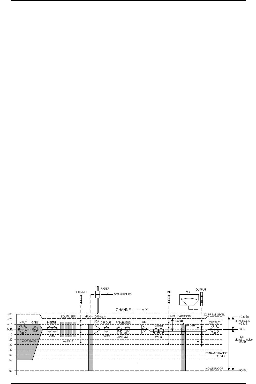
Gain Structure Notes for the user.
How the levels between the different signal stages
are set up is referred to as the gain structure. For
best performance it is important that the connected
source signals are matched to the ‘normal operating
level’ of the console. Similarly the levels of the
connected amplifiers and destination equipment
should be correctly matched to the console outputs.
If set too high then the signal peaks will be clipped
resulting in distortion, and if set too low then the
signal-to-noise performance will be degraded
resulting in excessive background hiss and noise.
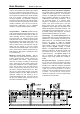
Using the Meters. The ML4000 provides metering
at all important stages through the signal chain. For
best results operate the console with the LED bar
meters averaging around ‘0’ allowing the loudest
moments to reach ‘+6’. Reduce the gain if the red
peak LEDs start to flash. Note that the peak leds
light 5dB before actual clipping to warn that you are
nearing distortion and should reduce gain. The
LED bar meters have a peak response with fast
attack and slow release so that fast musical
transients are accurately displayed. The VU meters
have a slower attack so that the average levels are
better displayed. Both types of metering are useful
in live sound mixing.
Matching a Source to the Console. Start by
turning down the channel fader and send levels to
prevent unexpected loud volumes reaching the
main speakers and monitors. Adjust the GAIN
control for an average ‘0’ reading on the channel
meter. Press PAFL (in PFL mode) to listen to the
signal using headphones, local or wedge monitor,
and to view its level on the main LED and VU
meters. Once the gain is correctly set you can raise
the levels to bring the channel into the mix. Note
that you may need to adjust the gain if you make
significant changes to the EQ. Make sure that any
equipment inserted into the channel is set to
operate around 0dBu line level. It is best to first set
the gain with inserted signal processors such as
compressors switched to bypass.
Matching the Console to Destination Equipment.
The console produces a standard XLR output level
of 0dBu for a meter reading of ‘0’. It can produce a
maximum of +23dBu and is therefore well suited to
driving equipment operating at nominal 0dBu or
+4dBu while providing plenty of headroom. If you
are connecting directly to a sensitive power
amplifier it is advisable to turn down its input trim
control if the normal console level is too high.
Simply turning down the console output faders
degrades the output stage noise performance and
reduces the resolution of the fader movement. The
output faders are best operated around ‘-10’ to ‘0’
for loudest average volume required. This allows
plenty of additional headroom if you need it.
Terminology. The normal operating level is the
optimum signal level for best console performance,
indicated by ‘0’ meter readings and resulting in the
0dBu output level. The channels operate at 0dBu
and the mix stages at –2dBu for extended
headroom. Headroom is the extra level available
above normal to allow for loud peaks before the
signal becomes clipped resulting in audible
distortion. The signal-to-noise ratio (SNR) is the
difference measured in dB between normal level
and residual noise floor (hiss) produced by the
console electronics. The dynamic range is the
sum of headroom and SNR representing the
maximum signal range possible from quietest to
loudest.
Using the VCA Groups. Assigning a channel to
one or more VCA groups lets those group faders
control the level of its VCA element. Each fader
provides up to +10dB boost. Note that the channel
VCA allows a maximum combined fader boost of
+10dB. Any more is simply ignored. It is best to
operate the VCA group faders around their nominal
‘0’ position. You can also use a VCA group to
reduce the overall level of a hot mix without having
to adjust all the channel faders.