
Operation Manual


32 ML5000 User Guide
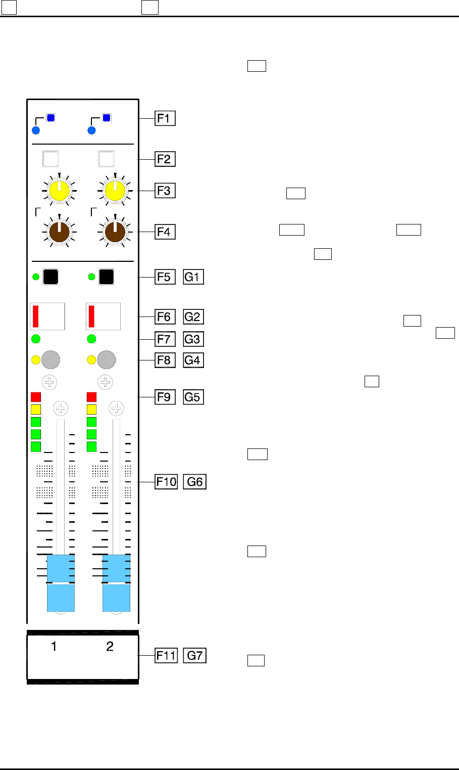
F GROUP / AUX 1-8 G AUX 9-16 MASTERS
F1 AUX/GRP MODE. This switch configures
each fader master 1 to 8 as either an audio group or
an auxiliary send. It is underpanel to protect it from
accidental operation. Use a pen or pointed
implement to select the required setting. The
default up position is flush with the panel.
In the up position GROUP MODE is selected. This
is the default setting for the front-of-house
application. The LED indicator lights to show that
group mode is active. In group mode, channel
switches B1 become the group routing switches.
These route the pre-pan signals for mono groups,
or post-pan for stereo groups according to channel
switch C4 . Channel rotaries B2 provide
independent post-fade aux sends to the rotary
master section H and are not associated with
these fader masters.
In the pressed position AUX MODE is selected.
This configures the master as an aux send for the
stage monitor application. The LED indicator turns
off. In aux mode, the channel rotaries B2 now mix
the signals to this master. Channel switches B1 ,
previously group routing switches in group mode,
now become pre/post-fader selectors for each send.
Note that the channel rotaries continue to feed the
independent rotary masters H with the post-fade
signals regardless of the setting of these pre/post
selectors. In this mode the rotary masters would
not normally be used.
F2 MAIN MIX. A single switch routes each
grp/aux 1 to 8 signal to the 3 output main mix.
Select this to create up to 8 subgroups to the main
mix. Its balance and image within the L, R and C
outputs is determined by the BLEND and PAN
controls.
F3 BLEND. This control adjusts the balance
between the LR and C outputs. Fully anti-clockwise
all the signal routes to the LR outputs and none to
C. At the detented centre position the signal routes
equally to the LR and C outputs. Fully clockwise all
signal routes to the C output and none to LR. The
control has a 3dB attenuation at centre position.
F4 PAN. Adjusts the balance between the L and
R outputs. It does not affect the C output. At the
detented centre position the signal routes equally to
L and R. PAN and BLEND combine to adjust the
balance between the 3 outputs. The control has a
3dB attenuation at centre position.
AFL
MUTE
SAFE/EDIT
PK
-6
SIG
+6
0
TB
AFL
MUTE
SAFE/EDIT
30
20
10
0
5
OO
LR C
=
LR
=
PAN
LCR
BLEND
+
MAIN
MIX
LR C
=
LR
=
PAN
LCR
BLEND
+
AUX
mode
GRP
AUX
mode
GRP
TB
MAIN
MIX
5
PK
-6
SIG
+6
0
30
20
10
0
5
OO
5