MixWizard WZ312M 16 Input 12 Mix Monitor Console USER GUIDE Publication AP6769
Limited One Year Warranty This product is warranted to be free from defects in materials or workmanship for a period of one year from the date of purchase by the original owner. To ensure a high level of performance and reliability for which this equipment has been designed and manufactured, read this User Guide before operating.
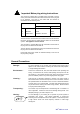
Important Safety Instructions WARNINGS - Read the following before proceeding : CAUTION ATTENTION: RISQUE DE CHOC ELECTRIQUE – NE PAS OUVRIR Read instructions: Retain these safety and operating instructions for future reference. Adhere to all warnings printed here and on the console. Follow the operating instructions printed in this User Guide. Do not remove cover: Operate the console with its covers correctly fitted.
Important Mains plug wiring instructions. The console is supplied with a moulded mains plug fitted to the AC mains power lead. Follow the instructions below if the mains plug has to be replaced.
Introduction Welcome to the Allen & Heath WZ3, the latest generation of the popular MixWizard series of compact audio mixing consoles. We have tried to keep this user guide brief and to the point. Please read it fully before starting. Included is information on installing, connecting and operating the console, panel drawings, system block diagram and technical specification.
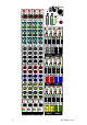
LAMP PHONES +48V +48V PAD PAD (LINE) 0 20 30 40 0 20 30 40 - 10 10 60 40 700 500Hz HM -15 70 180 +15 70 1k -15 +15 OO MIX 2 OO +15 MIX ST MIX OO L MIX MIX MIX ST ST ST ST MIX 3 OO +6 C PAN MIX 4 3 OO +6 C PAN MIX 4 L OO L MIX OO OO MIX 6 OO +6 OO L +6 OO OO OO +6 C PAN MIX MIX 8 L MIX 8 L +6 OO +6 OO L +6 OO OO +6 C PAN PAN MIX L PAN L MIX 10 +6 OO R +6 OO +6 OO MIX ST ST ST MIX 11 OO +6 C PAN
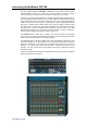
Introducing the MixWizard WZ312M The Allen & Heath MixWizard WZ312M Is a dedicated monitor console. With 16 mic/line channels feeding 12 mixes in a compact 19” rack mount frame it is ideal for personal monitoring systems touring with a show or installed on stage where space is tight.
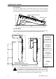
Installing the Console Free Standing The console is supplied ready for free standing operation with its side trims fitted and connector pod positioned for rear access.
Connecting Power FUSE CAUTION T630mA L 250V 20mm EXTERNAL DC IN AC MAINS IN ~ 100 - 240V~ 47-63Hz 45W MAX RISK OF ELECTRIC SHOCK DO NOT OPEN OFF ON 0 I AVIS: RISQUE DE CHOC ELECTRIQUE - NE PAS OUVRIR. CAUTION: FOR CONTINUED PROTECTION AGAINST RISK OF FIRE REPLACE FUSE WITH SAME TYPE AND RATING. ATTENTION: REMPLACER LE FUSIBLE AVEC UN DES MEMES CARACTERISTIQUES. WARNING: TO REDUCE THE RISK OF ELECTRIC SHOCK DO NOT EXPOSE THIS APPARATUS TO RAIN OR MOISTURE.
WZ312M User Guide L- 37 R- 36 GRP 1- 35 GRP 2- 34 GRP 3- 33 GRP 4- 32 AUX 1- 31 AUX 2- 30 AUX 3- 29 AUX 4- 28 AUX 5- 27 AUX 6- 26 PFL- 25 AFL- 24 nc 23 nc 22 nc 21 nc 20 19 0V (CHS) 18 L+ 17 R+ 16 GRP 1+ 15 GRP 2+ 14 GRP 3+ 13 GRP 4+ 12 AUX 1+ 11 AUX 2+ 10 AUX 3+ 9 AUX 4+ 8 AUX 5+ 7 AUX 6+ 6 PFL+ 5 AFL+ 4 nc 3 PFL DC 2 AFL DC 1 0V (PAFL)
Audio Connections The MixWizard uses professional grade 3 pin XLR and 1/4" TRS (3 pole) jack sockets. To ensure best performance, we recommend that you use high quality audio cables and connectors, and take time to check for reliable and accurate cable assembly. It is well known that most audio system problems are due to faulty or sub standard interconnecting leads.
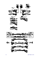
The Console Connectors ALLEN&HEATH INSERT INSERT INSERT INSERT INSERT INSERT INSERT IN IN IN IN IN IN SPLIT SPLIT SPLIT SPLIT SPLIT SPLIT 16 15 14 EXT MONITOR IN R L 13 R MONITOR OUT L 12 11 MixWizard WZ3 12M GROUND LIFT INSERT INSERT INSERT INSERT INSERT INSERT INSERT INSERT INSERT IN IN IN IN IN IN IN IN IN IN SPLIT SPLIT SPLIT SPLIT SPLIT SPLIT SPLIT SPLIT SPLIT SPLIT 10 9 INSERT 7 6 INSERT INSERT 5 4 INSERT 3 INSERT INSERT INSERT
SEND RETURN INSERT CHANNEL INSERT A single 3-pole TRS jack carries the unbalanced TIP RING insert signal. Tip = send, Ring = return, Sleeve = common ground. The channel insert is post-HPF, pre-EQ and operates at 0dBu. Use these to patch in line level signal processing equipment such as compressors, gates or outboard EQ. The wiring of a suitable cable is shown in the diagram: MIX INSERT Each mix is provided with an insert socket for patching in an outboard signal processor.
The Input Channels +48V Switches +48VDC to the channel input XLR for powering microphones or DI boxes that need phantom power. The power is current limited through 6k8 ohm resistors to pins 2 and 3. +48V PAD (LINE) 0 20 30 40 GAIN G 50 - 10 10 60 40 WARNING: Do not connect unbalanced sources or cables to inputs with phantom power selected. To avoid loud clicks always mute the channel before switching +48V on or off and when plugging or unplugging microphones.
MIX SENDS These rotary controls adjust how much channel signal +48V PAD (LINE) 0 20 30 40 GAIN G 50 - 10 10 60 40 is sent to the 12 mix outputs. Each has its own control. They adjusts from fully off to +6dB boost. Unity gain 0dB is marked at 3 o’clock position.
The Mix Masters MUTE Turns off the mix output. Affects the meter but does not affect the mix AFL function. This means you can mute the output while checking the post-fade mix signal using the console headphones and engineer’s monitor output. AFL Listen to the mix output in mono or stereo. Routes the postfade, pre-mute mix output to the engineer’s monitor system. The yellow LED lights when AFL is selected.
The Engineer’s Monitor The console provides left and right engineer’s monitor outputs on XLR and TRS jacks. The monitor signal is also fed to a built-in headphone amplifier with ¼” and 3.5mm output jacks. An AFL (after fade listen) function is provided to monitor the mix output signal. This is interrupted by pressing a channel PFL (pre fade listen) switch. An external input lets the engineer add an external stereo signal such as in-ear transmitter monitor output or talkback feed to the AFL mix.
Gain Structure How the levels between the different signal stages are set up is referred to as the gain structure. For best performance it is important that the connected source signals are matched to the ‘normal operating level’ of the console. Similarly the levels of the connected amplifiers and destination equipment should be correctly matched to the console outputs.
Specifications Performance Maximum output level XLR Jack +26dBu into 600 ohms max load +21dBu into 2k ohm max load Internal headroom Channels Mix Meters Sensitivity Master meters Channel meters 3 colour LED, quasi peak response 0VU = +4dBu at XLR output 12 segment -30 to +16dB 2 segment -12, +16dB (5dB before clip) Frequency response 20Hz to 50kHz THD+n at +10dBu 1kHz Channel to mix out < 0.
Connections Mono channel XLR balanced pin 2 hot Pad in Pad out Pad in Max input level XLR phantom power Sensitivity -60 to +10dBu Sensitivity -40 to +10dBu 2k ohm >10k ohm, -20dB +30dBu +48V, on/off Ext Input TRS unbalanced >5k ohm, 0dBu Inserts Channel Output Mix outputs XLR balanced pin 2 hot Monitor output TRS impedance balanced <75 ohm, -2dBu, +21dBu max XLR balanced pin 2 hot <75 ohm, +4dBu, +26dBu max Headphones TRS, tip L, ring R, 30 to 600 ohm headphones recommended Lamp 4-pin XLR TRS
AFL PFL M/S MODE WZ3 12M 12 MIX WEDGE / IEM MONITOR CONSOLE MIX 1-12 System Block Diagram PFL PHANTOM POWER 48V 4 BAND EQUALISER HF PAD -20dB 2= + LIFT + - MIX 1-2 PK PK GAIN IN MONO/STEREO MODE PK SIG HPF HM CH TRIM EQ IN LM SPLIT MIX 3-4 MUTE MIX 5-6 MIX 7-8 POST-FADE MIX 9-10 LF INSERT 0dBu DIRECT OUT B POST-EQ TIP= SEND MIX 11-12 PRE-FADE A PRE-EQ RING= RETURN C PRE-INSERT D PRE-FADE E POST-FADE PK SIG PK MODE MONO SOLDER PAD OPTION PRE STEREO MIX1 MIX2 INPU
WZ312M Monitor Console Cue Sheet Copy and use this page to record your console settings.