MixWizard WZ3 16:2 and WZ3 12:2 USER GUIDE Publication AP5331
Limited One Year Warranty This product is warranted to be free from defects in materials or workmanship for a period of one year from the date of purchase by the original owner. To ensure a high level of performance and reliability for which this equipment has been designed and manufactured, read this User Guide before operating.
Important Safety Instructions WARNINGS - Read the following before proceeding : CAUTION ATTENTION: RISQUE DE CHOC ELECTRIQUE – NE PAS OUVRIR Read instructions: Retain these safety and operating instructions for future reference. Adhere to all warnings printed here and on the console. Follow the operating instructions printed in this User Guide. Do not remove cover: Operate the console with its covers correctly fitted.
Important Mains plug wiring instructions. The console is supplied with a moulded mains plug fitted to the AC mains power lead. Follow the instructions below if the mains plug has to be replaced.
Introduction Welcome to the Allen & Heath WZ3, the latest generation of the popular MixWizard series of compact audio mixing consoles. We have tried to keep this user guide brief and to the point. Please read it fully before starting. Included is information on installing, connecting and operating the console, panel drawings, system block diagram and technical specification.
LAMP +48V +48V 0 -5 GAIN PAD (LINE) 0 20 30 (LINE) 0 40 GAIN 50 - 10 10 60 40 20 30 ON 5 CHAMBER TO 60 40 TO 9-10 TO (ST1+ST2) TO 10 1k HM 6k 15k 500Hz 1k 700 HM 70 180 +15 ON 45 400 35Hz LM 1k 180 10 +6 -20 16 OO +15 HM -15 +15 HM 12 SLAP+REV 1k 1 9 16 PH+REV 2 10 DUAL 3 11 4 12 3 HALL 5 13 4 PLATE 6 14 7 15 8 7 ARENA -15 +15 LM -15 +15 LM +6 OO 14 ECHO+REV 6 CATHEDRAL 400 35Hz LEV 13 DLY+REV 5 CHAMBER 250 ST6 4 15 CH
Introducing the MixWizard The Allen & Heath MixWizard series of consoles includes several models. This user guide 3 3 3 describes the WZ 16:2 and WZ 12:2 stereo models. The 4 group WZ 14:4:2 and stereo input WZ20S consoles are described in separate publications. For further information on the MixWizard series please refer to the Allen & Heath web site. The MixWizard is a compact console designed for professional live sound mixing.
Installing the Console Free Standing The console is supplied ready for free standing operation with its side trims fitted and connector pod positioned for rear access.
Connecting Power FUSE CAUTION T630mA L 250V 20mm RISK OF ELECTRIC SHOCK DO NOT OPEN EXTERNAL DC IN AC MAINS IN ~ 100 - 240V~ 47-63Hz 45W MAX OFF ON 0 I AVIS: RISQUE DE CHOC ELECTRIQUE - NE PAS OUVRIR. CAUTION: FOR CONTINUED PROTECTION AGAINST RISK OF FIRE REPLACE FUSE WITH SAME TYPE AND RATING. ATTENTION: REMPLACER LE FUSIBLE AVEC UN DES MEMES CARACTERISTIQUES. WARNING: TO REDUCE THE RISK OF ELECTRIC SHOCK DO NOT EXPOSE THIS APPARATUS TO RAIN OR MOISTURE.
WZ316:2 and 12:2 User Guide L- 37 R- 36 GRP 1- 35 GRP 2- 34 GRP 3- 33 GRP 4- 32 AUX 1- 31 AUX 2- 30 AUX 3- 29 AUX 4- 28 AUX 5- 27 AUX 6- 26 PFL- 25 AFL- 24 nc 23 nc 22 nc 21 nc 20 19 0V (CHS) 18 L+ 17 R+ 16 GRP 1+ 15 GRP 2+ 14 GRP 3+ 13 GRP 4+ 12 AUX 1+ 11 AUX 2+ 10 AUX 3+ 9 AUX 4+ 8 AUX 5+ 7 AUX 6+ 6 PFL+ 5 AFL+ 4 nc 3 PFL DC 2 AFL DC 1 0V (PAFL)
Audio Connections The MixWizard uses professional grade 3 pin XLR and 1/4" TRS (3 pole) jack sockets. To ensure best performance, we recommend that you use high quality audio cables and connectors, and take time to check for reliable and accurate cable assembly. It is well known that most audio system problems are due to faulty or sub standard interconnecting leads.
MixWizard WZ3 16:2 ALLEN&HEATH INSERT L 16 INSERT 15 INSERT 14 13 INSERT INSERT 12 11 INSERT 10 INSERT INSERT 9 INSERT 8 INSERT 7 INSERT 6 INSERT 5 INSERT 4 INSERT 3 INSERT 2 1 INSERT INSERT R LINE IN LINE IN LINE IN LINE IN LINE IN LINE IN LINE IN 16 15 14 13 12 11 10 9 8 7 6 5 4 3 2 1 MIC MIC MIC MIC MIC MIC MIC MIC MIC MIC MIC MIC MIC MIC MIC MIC DIRECT OUT 16 DIRECT OUT 15 DIRECT OUT 14 DIRECT OUT 13 DIRECT OUT 12 DIRECT OUT
The Console Connectors MIC / LINE IN The channel PAD (LINE) switch selects either the MIC INPUT +IN 1 2 XLR or the LINE TRS jack as the input source. The XLR is normalled through the TRS jack. This means that the XLR can be used for microphone or line level signals when nothing is plugged into the jack socket. Both inputs are balanced but can be wired to work with unbalanced signals when required.
L, R, M OUT The main console mix outputs are on balanced XLR. These produce +4dBu when the meters read ‘0’. The M output can be switched to provide a mono sum of the post-fade L and R signals, or the AUX6 output. The L and R outputs typically feed the house PA system in live sound mixing, or a 2-track recorder in studio mixing. In mono mode, the M output can provide an additional feed for a mono fill speaker or zone, or be used as the main feed into a mono PA.
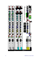
The MONO Input Channel +48V PAD (LINE) 0 20 30 40 GAIN 50 - 10 10 60 40 HPF HF -15 1k 6k 15k 500Hz PAD (LINE) Press this switch to select the channel TRS jack LINE -15 70 180 +15 250 45 LM LF WARNING: Do not connect unbalanced sources or cables to inputs with phantom power selected. To avoid loud clicks always mute the channel before switching +48V on or off and when plugging or unplugging microphones.
+48V PAD (LINE) 0 20 30 AUX SENDS These rotary controls adjust how much channel signal is mixed to the aux outputs. Each of the 6 auxes has its own control. They adjusts from fully off to +6dB boost. Unity gain 0dB is marked at 3 o’clock position.
The STEREO Input Channel 0 -5 GAIN 5 -10 10 -20 16 OO ON TO TO 11-12 0 -5 GAIN LR (ST3+ST4) 5 -10 10 -20 16 OO ON ( WZ312:2 only) Dual stereo inputs Each of the two stereo channels has two stereo inputs which can be used separately, mixed together or split so that one feeds the channel, the other routes direct to LR. For example, you could mix two sound effects playback devices or two reverb returns together into one channel.
The STEREO Effects Processor The MixWizard WZ316:2 and WZ312:2 features a built-in stereo digital effects processor. This can be configured to work as a single effects engine fed from AUX5, or in dual mode as two effects engines independently fed from AUX5 and AUX6. The processed signal is routed back to the mix through the ST1 (ST5) stereo return channel. In dual mode the two stereo effects mix together into the return channel.
The Stereo Effects Return Channel AUX SENDS FACTORY PRESETS AUX 1 SINGLE 1 STAGE 2 ROOM OO +6 OO +6 OO +6 OO +6 AUX 2 3 HALL 4 PLATE 5 CHAMBER 6 CATHEDRAL 7 ARENA 8 GATED REV AUX 3 9 KARAOKE 10 PING PONG 11 CHORUS 12 SLAP+REV AUX 4 13 DLY+REV 14 ECHO+REV 1 9 16 PH+REV 2 10 DUAL 3 11 4 12 3 HALL 5 13 4 PLATE 6 14 15 CH+REV 1 STAGE 2 ROOM 5 CHAMBER 6 CATHEDRAL 7 ARENA 7 15 8 16 8 GATED REV BANK 9 STAGE 10 ROOM SEL 11 HALL 12 SLAP DLY 13 DELAY ST5 / FX LEV 14
MIDI A rear panel MIDI IN socket is provided. This lets you control the internal effects via MIDI. For example, you could use a MIDI sequencer or controller to remotely change the preset type or to mute the effect. MIDI is also used for editing the effects preset parameters using Allen & Heath software running on a PC. MIDI channel number The factory default is MIDI channel 1. To change to a different channel hold down the BANK key while powering up the console.
The Master Section AUX MASTERS Each aux mix has a master level control that adjusts the output level to match external equipment, or to trim the monitor, effect or other send without affecting the mix balance. Up to +4dB boost is available above the normal 0dB position. PRE AUX 1 AUX 1 OO +4 OO +4 1-2 AUX 2 AUX 2 AUX 3 Note that the AUX5 and AUX6 master controls do not affect the level sent to the internal effects processor.
PHONES 0 OO TO LR +16 +9 +6 +3 0 -3 -6 -9 -12 -16 -20 -30 With the mode switch in its up position, the LR mix is selected as the source to the AB output TRS jacks. Factory default setting is post-LR fader. If preferred you can change this to pre-LR fader by repositioning internal option jumpers so that the LR master fader movements do not affect the output.
Gain Structure How the levels between the different signal stages are set up is referred to as the gain structure. For best performance it is important that the connected source signals are matched to the ‘normal operating level’ of the console. Similarly the levels of the connected amplifiers and destination equipment should be correctly matched to the console outputs.
Specifications Performance Maximum output level XLR Jack +26dBu into 600 ohms max load +21dBu into 2k ohm max load Internal headroom Channels Mix Meters Sensitivity Master meters Channel meters 3 colour LED, quasi peak response 0VU = +4dBu at XLR output 12 segment -30 to +16dB 2 segment -12, +16dB (5dB before clip) Frequency response 20Hz to 50kHz THD+n at +10dBu 1kHz Channel to mix out < 0.
Connections Mono channel XLR balanced pin 2 hot TRS balanced, tip hot Pad out (MIC) Pad in (MIC or LINE) Max input level XLR phantom power Sensitivity -60 to +10dBu Sensitivity -40 to +10dBu 2k ohm >10k ohm, -20dB +30dBu +48V, on/off Stereo channel ST1,3 TRS unbalanced ST2,4 TRS balanced >10k ohm, -16 to +20dBu >10k ohm, -16 to +20dBu Stereo returns ST1(5) TRS balanced ST2(6) TRS unbalanced >10k ohm, -6 to +20dBu >2k ohm, -2 to +20dBu Inserts Channel Output L, R, M outputs XLR balanced pin 2 hot
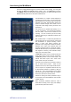
SYS-LINK CONNECTION AUX 1-6 LEFT RIGHT PFL 3 WZW 16:2 Z3 16:2 PHANTOM POW ER 4 BAND EQ UALISER PK SIG 48V SL AUX SENDS 1-6 PFL HF M IC LINE (PAD) -20dB 2= + BA LANCED + - HM H PF M UTE PAN TIP= + AUX1-6 TO M ONITOR -2dBu IMPEDANCE BA LANCED LF TIP= SEND 0dBu + 4dBu BAL OPTION AU X5,6 TO FX, AUX6 TO C FADER LINE INSERT AUX OUT AUX MIX LM TIP= + M ASTER SL G AIN POST-EQ RING = RETURN PRE-INSERT, PRE-EQ L B PFL DC PRE PFL M IX SL M IC/LINE INPUTS 0dBu M O NITO R M ETER
SYS-LINK CONNECTION AUX 1-6 LEFT RIGHT PFL 3 WZWZ3 12:2 12:2 PHANTOM POWER 4 BAND EQUALISER PK SIG 48V SL AUX SENDS 1-6 PFL HF GAIN MIC LINE (PAD) -20dB 2= + BALANCED + - HM HPF MUTE PAN AUX MIX TIP= + +4dBu BAL OPTION AUX1-6 TO MONITOR FADER LINE 0dBu -2dBu IMPEDANCE BALANCED LF TIP= SEND INSERT AUX OUT AUX5,6 TO FX, AUX6 TO C LM TIP= + MASTER SL POST-EQ RING= RETURN L B PRE-INSERT, PRE-EQ PFL DC PRE PFL MIX SL MIC/LINE INPUTS 0dBu MONITOR METERS PFL ACTIVE PRE-F
FX Parameters: This table shows the factory default preset settings. These may be edited via MIDI using the Allen & Heath MixWizard FX Editor software running on a PC.
FX Types Available: This table shows the effects types available. You may change the factory defaults to other types shown here using the FX Editor software. Note that effects type W can only be used in single mode. Effects type H can be used in both single and dual mode.
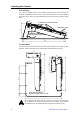
User Options REMOVE 4x M4 POZI SCREWS PER SIDE REMOVE SIDE TRIMS The MixWizard has a versatile architecture which should satisfy most applications you may encounter without modification. However, the following internal options provide alternative settings for those applications that may demand them. Access is required to the internal assemblies. For user convenience, pluggable jumper links are used in most places.
Aux pre/post insert/EQ MONO CH - AUX PRE/POST EQ L K J I H G F E D C B A PO SW PO SW PR SW PR SW PO PR PO PR AUX 6 5 3-4 1-2 DIR AUX PRE-INSERT/POST-EQ MONO CH - DIRECT OUT L K J I H Factory default for the mono channel pre-fade auxes is pre-insert, preEQ. This is popular with many users mixing monitors from FOH. It prevents the channel EQ and inserted compressors affecting the monitor mix. Move the jumper from A to B to change this to post-insert, post-EQ if preferred.
AUX master balance option AUX MASTER - BALANCED OUTPUT OPTION U12 U11 U10 U9 U8 U7 1 AUX6 AUX5 AUX4 AUX3 AUX2 AUX1 CUT OUT 2x 0 OHM RESISTOR LINKS PLUG IN SSM2142 or DRV134 IC The 6 aux outputs are impedance balanced as standard operating at nominal -2dBu and with +21dBu maximum drive. They provide similar interference rejection to electronically balanced outputs when connected to balanced equipment inputs.
WZ312:2 Cue Sheet Copy and use this page to record your console settings.
WZ316:2 Cue Sheet Copy and use this page to record your console settings.