
User guide


iPS10 User Guide 5
Introduction
This user guide presents a quick reference to the iPS10 digital console power supply
unit. We recommend that you read this fully before starting. Included is information on
installing, connecting and operating the power supply unit along with panel drawings
and technical specification. Whilst we believe the information in this guide to be reliable
we do not assume responsibility for inaccuracies. We also reserve the right to make
changes in the interest of further product development.
We are able to offer further product support through our worldwide network of approved
dealers and service agents. You can also access our Web site (www.allen-heath.com)
for information on our company and its pedigree, our full product range and our design
philosophy. To help us provide the most efficient service please keep a record of your
power supply unit serial number, and date and place of purchase to be quoted in any
communication regarding this product. The serial number is located on the rear panel.
Check the Packing Contents
Retain the product packing should you need to ship the product in future. You should find the
following components:
1x iPS10 POWER SUPPLY UNIT. This is packed with its
rubber feet fitted. The feet can be removed for rack
mounting.
1x IEC MAINS LEAD with moulded plug. Check that the
plug is suitable for connection to your local mains
supply.
iPS10/n
Where n = mains voltage 120 (USA), 220 (EU), 240 (UK)
120 USA, 220
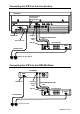
1x DC POWER CABLE 2.8m male>female 10-pin.
Part number 003-576. Connects the iPS10 power rails
to the iLive Surface or iDR0 MiniRack backup supply
input.
1x CAT5 CABLE 2.8m RJ45 connections.
Part number AH6831. Connects the iPS10 to the iLive
Surface or iDR0 MiniRack backup temperature monitor
input.
DOCUMENTATION including the User Guide AP6688,
Safety Sheet AP3345, and the Registration Card
AP3594.
ADVANCED POWER SUPPLY TECHNOLOGYDIGITAL SYSTEM BACKUP SUPPLY
POWER ON
POWER
ON
OFF
iPS10 ALLEN&HEATH