GS1 compact 8 buss console SERVICE MANUAL PUBLICATION AP2064
INTRODUCTION The information presented in this manual is intended for competent technical personnel to carry out service and product support for the GS1. We assume that the reader is familiar with the related electronic theory and audio terminology, and is able to carry out basic servicing, fault-finding and repair of audio equipment of this type. Service personnel should also be familiar with audio systems, mains earthing and power requirements, as well as handling precautions.
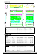
DIMENSIONS PSU METERBRIDGE GS1 EXPANDER Dimensions packed W D H unpacked Kg(lb) packed Kg (lb) GS1 .................................................................... 630 ..... 550 ..... 140 .................. 7.5 (16.5) ...................... 10.5 (23.1) EXPANDER ....................................................... 400 ..... 550 ..... 140 .................. 5 (11) ............................ 7 (15.4) METERBRIDGE ................................................ 630 ..... 100 ..... 140 ..........
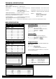
TECHNICAL SPECIFICATION 0 dBu = 0.775 Volts RMS 0 dBV = 1 Volt RMS Line level options: +4dBu (high level), -10dBV (low level) MAX OUTPUTS: .......................... unbalanced +21 dBu 2kohms max load FREQUENCY RESPONSE: 10Hz to 30kHz +0/-1dB METERS: ..................................... 8 segment bargraphs for L,R -20VU to +6VU (peak) 0VU = +4dBu or -10dBV as selected DISTORTION: THD 0.006% Line in to mix out at 1kHz POWER REQUIREMENTS: ........ 33VA max.
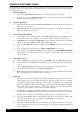
CONSOLE FUNCTIONAL CHECK The GS1 undergoes several rigorous stages of testing and quality control before being despatched from the factory. The following procedure is offered to the distributor, dealer and customer to confirm that the unit has arrived without damage and in full working order. 1. Packing inspection 1.1 Check that the packed unit is intact and has not suffered unreasonable transit damage. 1.2 2. Cosmetic inspection 2.1 Carefully unpack the unit and check general cosmetic quality.
Replug and repeat for Channels 2 to 8. 5.4 Plug CD L and R into Channel 9/10 STEREO RTN jack sockets. Raise and test the RTN Level and Pan pots. Replug and repeat for Channels 11/12 to 15/16. 5.5 Plug CD L and R into Channel 9/10 Stereo Input jack sockets. Raise channel Fader to ‘0’ and press LR. Test Fader, Hi/Lo switch, EQ, Pan and Channel On functions. 5.6 Plug CD into Channel 1 Line input jack socket. Raise Fader to ‘0’, route to 1-2. Link GROUP Out 1 phono socket to TAPE RTN In phono socket.
CONSOLE DISASSEMBLY rear view side view Figure 1. Stage 1 - Removing the front panel. Refer to figure 1. 1. Remove the 4x screws (27) and 2 shakeproof washers (8) from the underside of the side extrusions. (13) 2. Remove the 4x screws (4) from the front end caps. (12) 3. Remove the front extrusion (15) with the plastic front end caps (12) still attached. 4. Remove the 2x screws (4) that attach the rear end caps (12) to the console chassis. 5.
Stage 2 - Removing the PCB. rear view side view Figure 2. Refer to figure 2. 1. Remove the 2x screws (4), the 2 locknuts (5) and the 2 plastic insulators (6) that attach the regulators to the rear panel. 2. Remove the 11x screws (3) from the phono connectors along the rear panel. 3. Remove the locknut (5) from front right stud. 4. Remove the nut (7) and shakeproof washer (8) from front left stud. 5.
EXPANDER DISASSEMBLY rear view side view Figure 3. Stage 1 - Removing the front panel. Refer to figure 3. 1. Remove the 4x screws (27) and 2 shakeproof washers (8) from the underside of the side extrusions. (13) 2. Remove the 4x screws (4) from the front end caps. (12) 3. Remove the front extrusion (15) with the plastic front end caps (12) still attached. 4. Remove the 2x screws (4) that attach the rear end caps (12) to the console chassis. 5.
Stage 2 - Removing the PCB. rear view side view Figure 4. Refer to figure 4. 1. Remove the 8x screws (3) from the phono connectors along the rear panel. 2. Remove the locknut (5) from the front right stud. 3. Remove the nut (7) and shakeproof washer (8) from the front left stud. 4. Carefully ease the PCB off the 6 plastic snap-in supports (10) by squeezing together top of supports with pliers or suitable tool.
EXPANDER OPTION FITTING INSTRUCTIONS The GS1 Expander Unit adds a further 8 channel strips giving 16 extra inputs. Please read the following instructions carefully before attempting to fit the Expander. Disconnect GS1 from Power Supply Unit and cables before fitting expander 1 1 2 3 Remove screws from left hand extrusion and rear end cap of GS1 and slide out extrusion as shown. It may be necessary to loosen screws "A" to enable extrusion to slide. Connect expander ribbon cables to the GS1 as shown.
METERBRIDGE OPTION FITTING INSTRUCTIONS The GS1 Meterbridge option provides the user with full Group and Left/Right metering. The Meterbridge has been designed to fit either at the rear of the console on the supports provided or at the front as a replacement for the existing armrest. Please read the following instructions carefully before attempting to fit the Meterbridge.
ASSEMBLY (REAR POSITION) As supplied the front panel and PCB are assembled in the extrusion the correct way round for mounting at the rear of the console. 2 1 Attach side trims ITEM 6 to the extrusion ITEM 7 using the self tapping screw supplied ITEM 2 The Left hand side trim has a rebate for the IDC cable. Care should be taken not to trap the cable when attaching the side trim. 3 Apply self adhesive facia ITEM 4 to the front panel ITEM 5 ensuring correct alignment with the meter slots.
Apply the self adhesive cable clip ITEM 3 as shown in the diagram. 6 Route cable as shown below. Replace side extrusion and rear end cap. The installation is now complete. Replug the console and test for correct operation. ASSEMBLY (ARMREST POSITION) 1 2 To assemble the Meterbridge in the armrest position the Front Panel/PCB assembly ITEM 5 must be removed from the extrusion ITEM 7 and replaced the opposite way round.
4 Remove screws from left hand extrusion and plastic end cap and slide out extrusion as shown. Remove left hand front end cap held by screws "A" and "B" 5 Release screws "B" from right hand front end cap and remove existing armrest. Insert Meterbridge into right hand front end cap, replace left hand front end cap ensuring IDC cable exits through the slot in the end cap.
ORDERING SPARE PARTS ORDERING A CONSOLE MODEL DESCRIPTION ORDER CODE GS1 240V 16 channel GS1 + PSU (240V) GS1/240 GS1 220V 16 channel GS1 + PSU (220V) GS1/220 GS1 120V 16 channel GS1 + PSU (120V) GS1/120 GS1 110V 16 channel GS1 + PSU (110V) GS1/110 GS1 100V 16 channel GS1 + PSU (100V) GS1/100 ORDERING AN OPTION MODEL DESCRIPTION ORDER CODE GS1 EXPANDER 8 channel Expander GS1-EX GS1 METERBRIDGE Group & L/R meterbridge GS1-MP ORDERING A POWER SUPPLY MODEL DESCRIPTION ORDER CODE 2
ORDERING A SPARES KIT It is recommended that the spares kit order code 002-014 is held and maintained by the service agent to enable in-field service repairs to the GS1 independent of the ALLEN & HEATH factory. Commonly available items such as resistors, capacitors, tools and soldering equipment are not included. The contents of the kit is listed here. Individual spare parts may be ordered. Please quote the description and order code for the part required.
DESCRIPTION IC IC IC IC IC IC IC IC IC IC IC IC ORDER CODE QTY TLO72 Dual Op Amp (SIL Package) LM339 Quad Comparator CMOS 4053B CMOS 4051B CMOS 4099B 6N136 Opto isolator Regulator 7815 (+15V DC) Regulator 7915 (-15V DC) Regulator 783 (+48V DC) CMOS 74HC4051SMD (Expander only) CMOS 74HCF4099 SMD (Expander only) TL072 Dual Op Amp (DIL Package) (Expander only) AE8070 AE0071 AE0117 AE0118 AE0238 AE0222 AE0047 AE0048 AE0214 AE2161 AE2162 AE0046 5 2 1 1 1 1 1 1 1 - AA0693 AA2168 AN2072 AL2119 AL2154 AL2155
TECHNICAL DIAGRAMS This section includes the circuit diagrams and illustrations plus any technical bulletins
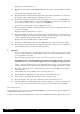
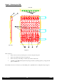
Aux 1 link options: Tape Return or Channel pre-fade ( 8 pairs) Phantom Power link options (PP or +48V) ( 8 off) 7 5 5 Sheet no: CH 1 1 CH 2 2 CH 3 1+4 CH 4 2+4 CH 5 1+4 PCB fig. I CH 6 CH 7 2+4 1+4 CH 8 2+4 CH 9/10 3 3+4 3+4 8 3+4 CH 11/12 CH 13/14 CH 15/16 7 PCB fig. II L-R 7 F KEYS 5+6 GS1 CONSOLE CIRCUIT DIAGRAM PCB KEY & LINK OPTION POSITIONS The areas outlined on the PCB correspond to the sheet number on the circuit diagram C2018.
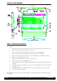
PCB COMPONENT LAYOUT FOR CHANNELS 1 TO 8 PCB fig.
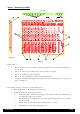
PCB COMPONENT LAYOUT FOR CHANNELS 9 TO 16 & MASTER L-R PCB fig.
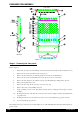
GS1 EXPANDER CIRCUIT DIAGRAM PCB KEY & LINK OPTION POSITIONS The areas outlined on the PCB correspond to the sheet number on the circuit diagram C2054.