GR8A 8 Channel Amplifier USER GUIDE Publication AP4298
Limited One Year Warranty This product has been manufactured in the UK by ALLEN & HEATH and is warranted to be free from defects in materials or workmanship for a period of one year from the date of purchase by the original owner. To ensure a high level of performance and reliability for which this equipment has been designed and manufactured, read this User Guide before operating.
CONTENTS Warranty............................................................................... 2 Safety Warnings................................................................... 3 Welcome to the Allen & Heath GR8A .................................. 4 General Precautions ............................................................ 4 Specifications ....................................................................... 5 Front Panel Controls ............................................................
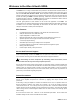
Welcome to the Allen & Heath GR8A The GR8A is one of a range of architectural sound products in the Allen & Heath Contractor Series. It is an 8 channel audio power amplifier designed to work with multi-output zoning mixers such as the Allen & Heath GR05, GR1, DR128 and DR66. Modern amplifier technology has enabled the GR8A to achieve multi-channel high power output in a relatively small case size.
Specifications Connections Input x8............................................ Balanced XLR pin 2 hot Speaker x8 ......2 pin Phoenix type pluggable screw terminal Headphones ........................................ TRS tip left, ring right Monitor........ Unbalanced TRS tip signal, ring, sleeve ground Remote standby ........................................ 9 pin D connector Battery backup......................... 4 pin Phoenix type pluggable AC mains input .................................................
Front Panel Controls POWER switch Turns the amplifier on or off. I = on, 0 = off.
Rear Panel Controls and Connectors MAINS INPUT The GR8A AC mains voltage setting is factory wired according to country of order. An IEC power lead with moulded plug suitable for your mains outlet is supplied with the unit. Check that the mains voltage marked on the rear panel matches your local supply. Read and heed all the warnings printed on the rear panel and at the start of this user guide.
REMOTE STANDBY 9-pin D-type female connector can be wired to external switches to remotely mute individual channels. Any combination of channels can be muted at the same time. Putting a channel into standby mutes its output driver stage. To mute a channel simply switch its connector pin to the common (+15V) pin. Do not connect the common pin to any other equipment. The front panel STANDBY indicator lights to warn that the channel is muted. Use shielded cable for long cable runs.
INSTALLATION The GR8A can be rack or desk top mounted. It is supplied with rack ears and desk feet fitted. These may be removed according to the installation required. RACK MOUNT The GR8A fits into a 2U space in a standard 19” rack system. The rack should allow a minimum side to side opening of 445mm and a depth of at least 420mm to include the connector space required. Secure the unit into the rack using two M6 bolts on each side.
OPERATION Switching On Connect all input and output cables to the unit, ensure it is correctly installed as described previously and that the input and bridge mode switches are set as required. Make sure the mains voltage setting is correct and the mains switch in the ‘0’ off position. Start with all level controls set minimum. Ensure that all equipment connected to the amplifier is turned on. Switch the unit on by pressing the mains switch to its ‘I’ position.
BLOCK DIAGRAM GR8A USER GUIDE 11