ALLEN&HEATH GR05 Audio Zone Mixer Introduction ......................... 3 Welcome to the GR05 ......... 4 22 M Miiccrroopphhoonnee IInnppuuttss 33 S Stteerreeoo LLiinnee IInnppuuttss 44 ZZoonnee O Ouuttppuuttss R Roouuttiinngg M Maattrriixx R Reem moottee C Coonnttrrooll The System.......................... 5 D Duucckkiinngg E Exxppaannddeerr Level Control........................ 16 Overview of Installation ....... 6 Positioning the Unit ............. 8 Connecting Power............... 9 Front Panel .
Limited One Year Warranty This product is warranted to be free from defects in materials or workmanship for a period of one year from the date of purchase by the original owner. To ensure a high level of performance and reliability for which this equipment has been designed and manufactured, read this User Guide before operating.
Safety Warning ! Do not remove the cover while mains is connected. Mains voltage is dangerous and can kill. Mains voltage is present within the unit. Do not carry out any work within the unit while it is powered except for installation calibration. High voltage components are insulated for safety but should not be touched with power applied. Do not attempt to remove the main circuit assembly from the chassis. Refer service work to qualified service personnel only. This equipment must be earthed.
Welcome to the GR05 The GR05 is a 1U rack or desk mount audio zone mixer for installation applications such as paging and background music systems in restaurants, retail outlets, leisure centres, clubs, theatres, business offices etc. It has a flexible architecture which allows easy custom configuration by the installer to exactly suit the requirements of the installation. Once installed it presents a simple control interface for day to day operation by non-technical staff.
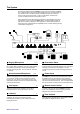
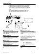
The System The following diagram shows the GR05 in a typical sound contractor installation. This combines paging microphones with background music sources feeding up to 4 speaker zones. An alarm interface and battery backup are included to ensure crowd control in the event of a fire or power failure. Remote level controls are wall mounted for local speaker control. Each installation has its own particular combination of input/output and control requirements.
Overview of Installation Before starting make sure you have read this User Guide and understand the full capabilities of the GR05. Plan the complete system first to decide how the GR05 should be configured. Make sure you know the operating levels of the equipment to be interconnected. To configure the unit you need to remove the top cover and set internal links and trimmers. These adjust input and output level matching, EQ, routing, ducking and level control.
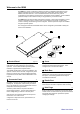
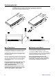
Rack or Desk Mount 8 The GR05 is shipped with the two rack ears and its plastic feet fitted. The unit will fit into a 1U space in a standard 19” industrial rack case. Use the bolts provided by the rack supplier to mount the unit in the rack. Remove the feet if required. You can also use the rack ears to mount the unit into a plinth. For desktop or shelf operation the rack ears can be removed. The plastic feet prevent the unit scratching the mounting surface or slipping.
Positioning the Unit The GR05 is built into a compact all steel case. This can fit into a standard 1U 19” rack space with the mounting ears provided. Alternatively the unit can be desk or shelf mounted by removing the ears. ALLEN&HEATH GR05 mic/line 1 mic/line 2 st line 3 st line 4 st line 5 out 1 out 2 out 3 out 4 mute ducking power AUDIO ZONE MIXER 19” Rack Mount The GR05 is shipped with the two rack mount ears and its plastic feet already fitted.
Connecting Power The GR05 has a built in mains operated power supply unit. This converts and conditions the mains voltage to the DC voltages required to power the circuits. An additional DC power input is available on the rear panel expander/remote connector. This lets you connect a backup power supply such as a battery unit which automatically takes over in the event of a mains power failure. Check the requirements of the installation regarding the specification of safety and power systems.
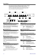
Front Panel The front panel control layout is deliberately uncluttered and simple. These are the controls that are used by the non-technical operator who does not need to understand how the unit has been configured or what the controls do technically. Control function and access can be configured by the installer. A row of 3-colour LED indicators display the signal levels and system status. These are invaluable for system setup and diagnostics.
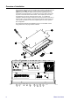
Rear Panel The audio input and output connectors, expander/remote interface connector, and mains input connector, fuse and switch are located on the rear panel. All connections are pluggable to allow pre-wiring of the cables before the unit is installed. The microphone input gain trimmers are also located on the rear to allow easy readjustment of mic sensitivity by the installer but not the operator. The factory set mains voltage and unit serial number are marked on the rear panel. 47-63Hz~ V.
Microphone/Line Inputs 1,2 This section describes the installer configuration of the microphone inputs 1 and 2. For each input you can select an attenuator pad, phantom power, lo-cut filter, adjust equalisation and configure the routing to the outputs. If microphones are not required you can still use these inputs for additional mono line sources. To configure the unit switch off power, remove the top cover and adjust the links and trimmers as shown. Power may be applied for setting up the trimmers.
Input Connector Plug in a standard microphone cable. Always use good quality 2-core screened cable. Use a 3-pin male XLR plug at the GR05 input. Pin 1 Pin 2 Pin 3 = 0V ground (screen) = Signal + (cold) = Signal – (cold) For unbalanced line level sources connected with 2-wire cable link Pin 3 to Pin 1 in the XLR plug. If you have problems with ground loop induced audible hum and buzz then first check that each piece of equipment has its own separate path to ground.
Line Inputs 3,4,5 This section describes the installer configuration of the stereo line inputs 3, 4 and 5. For each input you can set the input sensitivity and configure the routing to the outputs. You can choose whether the channel is stereo, mono or combines two inputs into mono. To configure the unit switch off power, remove the top cover and adjust the links as shown. Avoid the power supply components shown greyed out on the diagram.
Zone Outputs 1,2,3,4 This section describes the installer configuration of the zone outputs 1,2,3,4. For each output you can adjust the level trim and equalisation. Front panel signal metering lets you keep a check on signal activity and warns of overload. The outputs provide line level signals which plug into the power amplifiers which drive the loudspeakers. Do not connect direct to speakers. To configure the unit switch off power, remove the top cover and adjust the trimmers as shown.
Level Control This section describes the installer configuration of the VCA path level control. For each output you can select which front panel control affects the level. This lets you control stereo zones or groups of outputs with a single level control. You can also assign which outputs will be turned on or off by the front panel switch. The switch function can be disabled if required. To configure the unit switch off power, remove the top cover and adjust the jumper links as shown.
Remote Control This section describes the installer configuration of the VCA path remote level control. For each output you can select whether the level is controlled by the front panel control or by remote DC voltage. Note that this does not affect signals which are routed through the DIRECT path to the outputs. To configure the unit switch off power, remove the top cover and adjust the jumper links as shown. Avoid the power supply components shown greyed out on the diagram.
Ducking Ducking provides an automatic voiceover or muting facility. Ducking is triggered by a ‘priority’ signal, for example a paging microphone. The level of the background music is reduced by a pre-determined amount when a priority audio signal is detected. When the priority audio signal is removed the ‘ducked’ music returns to normal level. In this way simply talking into the paging microphone automatically overrides the music. When you stop talking the music returns smoothly to normal level.
External Ducking Trigger External ducking is triggered by linking Pin 11 of the expander / remote connector to Pin 8 (0V ground). Wire these pins to a switch or relay. Closing the switch contacts triggers ducking. Equipment such as alarm and jukebox systems often provide trigger outputs suitable for direct connection to these pins. Opto-Isolated Input The external ducking trigger input is opto-isolated (coupled) to avoid interference from external controllers.
Input / Output Expander This section describes the installer connection and configuration of expander inputs and outputs. These may be configured to provide additional inputs or outputs, or wiring of special functions such as an alarm system interface. These connections are part of the 25-pin D-type female connector which also includes the remote control and battery backup connections. You can also use the expander outputs as an alternative connector system instead of the XLR outputs.
Specification System Output level control High performance VCA system Front panel or remote DC control, assignable mute Ducking Internal triggered by Mic1 and/or Mic2 External triggered by opto-isolated remote input Selectable -10dB, -20dB, mute, fast, slow Routing Assignable 9 x 4 x 2 crosspoint matrix OFF, DIRECT or VCA paths to each output Signal meters 3-colour LED for each input and output Green = signal (–12dB), yellow = 0dB, red = peak (+15dB) Mic1,2 equalisers LF ±12dB 70Hz shelf, H/MF ±14d
GR05 User Guide GR05 AUDIO ZONE MIXER ALLEN&HEATH
GR05 User Guide 23 47-63Hz~ V.AC mic/line 1 100-120V ~ = T630mAL 250V 20mm 220-240V ~ = T315mAL 250V 20mm FUSE S/No 18W MAX THIS APPARATUS MUST BE EARTHED. CAUTION: RISK OF ELECTRIC SHOCK. HIGH VOLTAGE INSIDE. AVIS: RISQUE DE CHOC ELECTRIQUE WARNING AUDIO ZONE MIXER GR05 ALLEN&HEATH AUDIO ZONE MIXER GR05 GR05 ALLEN&HEATH CONFORMS TO UL STD. 6500 CERTIFICATED TO CAN/CSA STD.
ALLEN&HEATH GR05 AUDIO ZONE MIXER GR05 User Guide 24