
User guide


GL2800 User Guide 27
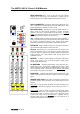
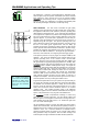
Using PFL / AFL Allen & Heath are renowned for bringing you
the most comprehensive engineer’s monitoring system in consoles at
this price point. We recognise the importance of correct gain structure
and signal handling. The GL2800 includes LED meters for every
input channel and main output, as well as a pair of high resolution
meters dedicated to monitor duty only. In monitor mode the M fader
and associated controls become a full featured PFL/AFL monitor feed
for the engineer’s listen wedge.
The input channels provide PFL (pre-fade listen) so that each source
can be checked using the meters and headphones before you bring
the fader up. You can even use PFL while the channel is muted to
prevent the signal reaching the house and monitor speakers until you
have checked it and are ready.
All the main and aux outputs provide AFL (after-fade listen) so that you
can check the exact level leaving the console. Once again, the AFL
switch gets its source before the output mute switch so that you can
check the signal before you send it to its destination. This can be very
important when you are feeding remote destinations such as
broadcast and recording.
The Decibel the ‘Bell’ is the unit of sound level. Decibel is 1/10
Bell, a more conveniently sized unit. dB = 20 log (Vo / Vi) where Vi
and Vo are two signal voltages, in and out (ignoring the impedances).
The dB is used to express the relationship between two levels, chosen
because of the logarithmic way our ears respond to sound. The ‘dB’
relates one level to another. For example, a preamp with a gain of
40dB (100x) would produce an output of +10dBu for an input of -
30dBu. Several audio standards exist to relate a signal level to a
known reference. Audio engineers need to deal with a variety of
equipment standards, for example, a -10dBV CD player plugged into a
console with +4dBu outputs connected to a 0dBu input DSP speaker
manager, or an operator using an SPL (sound pressure level) meter to
measure sound intensity.
dBu Relative to 0.775Vrms – professional standard
0dBu = 0.775V +4dBu = 1.228V
dBV Relative to 1Vrms - consumer audio standard
0dBV = 1V -10dBV = 316mV = -8dBu
dB-A Sound pressure with a filter contour to approximate
the response of the human ear. Three curves A, B,
C exist for different loudness.
dBfs Relative to signal maximum before clip (full scale)
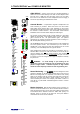
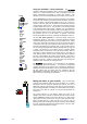
Using Inserts The GL2800 channel inserts operate at 0dBu,
the output inserts operate at -2dBu. In practice this makes little
difference as long as the inserted equipment is intended for line level
operation (-6 to +4dBu). Simply set the gain through the device to
unity (0dB) with the bypass switch pressed (if available). With the
effect switched in, use the console channel gain control to make any
further adjustments needed. This keeps the gain structure correct
through the channel signal path.
With nothing plugged into the insert, the channel signal is routed
through a switching (‘normalling’) contact in the socket. As soon as a
jack is plugged into the socket the contact is opened and the signal
path broken so that the external device can be patched in series with
the signal.
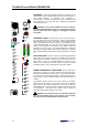
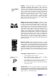
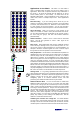
AFL
dB
SEND
INSERT
RETURN
TIP
RING
☺ If you suspect the insert
socket to be faulty or
intermittent through excessive
wear or contamination, test for
this by plugging in a jack with
its tip shorted to its ring
contact. This bypasses the
contact in the socket. Clean
using suitable electrical
contact cleaner.
Tech talk…
For an audio circuit stage:
Pi = Input signal power
Po = Output signal power
The Decibel is defined as:
dB = 10 log (Po / Pi)
= 10 log (Vo
2
/Ro / Vi
2
/Ri)
If input and output impedances
Ri and R0 are the same, then:
dB = 20 log (Vo / Vi)
dBm is defined as 1mW into
600 ohms = 0.775V
dBu = 0.775V ignoring the
600 ohms as we assume high
input and low output
impedance and therefore
maximum voltage transfer
between stages, appropriate
for modern audio.
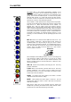
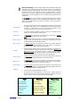
Note: The stereo Aux 9-10
and matrix 1-4 outputs can
be monitored using the
monitor select switch bank.
This provides true stereo
monitoring of these mixes.
PFL/AFL automatically
overrides any source
selected on this
switchbank.