
User guide


14 GL2800 User Guide
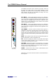
The Console Connectors
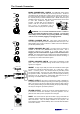
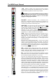
MONO CHANNEL MIC / LINE IN The LINE (PAD) switch selects
either the MIC XLR or the LINE TRS jack as the input source. The XLR is
normalled through the TRS jack so that it can be used for microphone or
line level signals when nothing is plugged into the jack socket. This gives
the channel preamp a massive headroom with +34dBu maximum input
capability using XLR or jack. Both inputs are balanced but can be wired
to work with unbalanced signals when
required. The MIC XLR can be switched to
provide +48V DC via 6k8 ohm resistors to
pins 2 and 3 for microphones such as
condensers which require phantom powering.
WARNING: Do not connect unbalanced sources or cables to
the XLR input when 48V phantom power is selected. To avoid loud
clicks always turn the channel off by pressing MUTE when switching
+48V on or off, and when plugging or unplugging cables.
STEREO CHANNEL MIC IN Each stereo channel features a
mono microphone XLR input and an independent stereo line input. The
balanced MIC input accepts a maximum +14dBu and can be switched to
provide 48V phantom power.
STEREO CHANNEL MIC OUT The output of the mic preamp is
available on the MIC OUT (BREAKPOINT) TRS jack socket. This is
impedance balanced and operates at a nominal 0dBu line level.
Plugging into this socket breaks the signal into the associated stereo
channel. This means that the mic preamp can be used independently of
the channel, for example to create an ambience mic feed for recording, or
as a preamp for an RTA measurement system.
STEREO CHANNEL LINE IN These inputs are balanced on TRS
jacks. The L input is normalled through the R socket to accept mono
signals on a single jack.
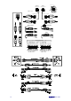
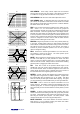
INSERT A single 3-pole TRS jack carries the unbalanced insert signal
for each mono channel and main mix output. Tip = send, Ring = return,
Sleeve = common ground. The channel inserts are post-HPF, pre-EQ
and operate at 0dBu. The group (aux) and LRM mix inserts are pre-fader
and operate at -2dBu. Use these to patch in line level signal processing
equipment such as compressors, outboard EQ, delay units and so on.
The wiring of a suitable cable is shown in the diagram.
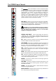
DIRECT OUTPUT Each mono channel direct output is available on
an impedance balanced TRS jack providing a line level signal operating at
0dBu. The source is set using an internal option jumper for each channel.
The factory default setting is pre-fade (following the pre/post-EQ setting).
This may be changed to post-fade if preferred.
TB/GEN OUTPUT Use this to provide an external talkback feed, or
to access the console 1kHz oscillator / pink noise generator. You can
patch this into other inputs or equipment as a test signal.
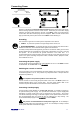
LAMP The console has two 4pin XLR sockets to plug in standard 12V
gooseneck lamps to illuminate the operating surface when working in a
dark environment. Only use lamps intended for this purpose. We
recommend the Allen & Heath LEDlamp with cool white LED illumination
and a built in dimmer.
OUT
INSERT
DIRECT
LINE IN
MIC IN
- IN
+IN
3
INPUT
2
1
RING -INRING
TIP +INTIP
LINE
MIC
GROUND
RETURN
SEND
RETURN
OUT
IN
SEND
PROCESSOR
LINK RING TO SLEEVE TO UNBALANCE
SEND
INSERT
RETURN
TIP
RING
LAMP
STEREO LINE IN
R
L/M
MIC OUT
(BREAKPOINT)
MIC IN
OUT
TB/GEN