
User guide


GL2800 User Guide 13
Audio Connections
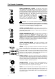
The GL2800 uses professional grade 3 pin XLR and 1/4" TRS (3 pole) jack sockets. To
ensure best performance, we recommend that you use high quality audio cables and
connectors, and take time to check for reliable and accurate cable assembly. It is well
known that most audio system problems are due to faulty or sub standard interconnecting
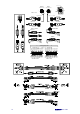
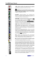
leads. The following plugs may be used to connect audio to the console:
Avoid reversing + and - on balanced connections as this will result in reversed polarity (out
of phase) signals which may cause signal cancellation effects.
Where long cables runs are required, balanced interconnections should be used. However,
line level interconnections between more affordable 2-wire (signal, ground) unbalanced
equipment and the console are unlikely to cause problems if the cables are kept shorter
than 10 metres or so. Refer to the wiring diagrams on the opposite page.
Dealing with Ground Loops, Buzz and Interference
For optimum performance all audio signals should be referenced to a solid, noise-free
ground (earth) point, frequently referred to as the ‘star point’ or ‘clean earth’.
A ground loop is created when potential differences exist between grounds at different
points in the system, and the signal has more than one path to ground. In most cases
ground loops do not result in audible problems. Should you experience hum or buzz
caused by a ground loop, check first that each piece of equipment has its own separate
path to ground. If so, operate ground lift switches on connected equipment in accordance
with the instruction manuals. Alternatively disconnect the cable screen at the destination
end only. This breaks the offending loop while keeping the signal shielding down the
length of cable.
WARNING For operator safety, do not remove the ground (earth) connection
in the power lead of the console power supply unit or connected equipment.
To avoid interference pickup keep audio cables away from mains power units and cables,
lighting cables, thyristor dimmer units, computer equipment and mobile phones. Where
this cannot be avoided, cross the cables at right angles to minimise interference
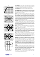
A note about balanced connections
A differentially balanced connection has two signal wires, signal + (hot) and signal - (cold)
and a shield. The signal source generates positive going polarity down the + wire and
negative polarity down the – wire. The destination input stage accepts the + signal on its
non-inverting (+) input pin, but it inverts the – signal, adding it to the + signal. The result is
that the wanted signal is boosted. Now examine what happens when unwanted
interference (hum and noise) is induced into the cable. The noise is induced equally and
with the same polarity into both wires. At the destination input the – wire signal gets
inverted and added to the + signal. Because the polarity is the same on both input wires
the noise cancels itself out at this input. For this interference rejection to work it is important
that the source, the cable and the destination input are all balanced. Balancing provides
greatest advantage with low level signals such as those produced by microphones.
An impedance balanced
output provides similar interference rejection, but not as much
maximum drive capability as the differentially balanced output, typically +20dBu versus
+26dBu. It does not generate a negative polarity signal at its – output. Instead, the – wire
has no signal but is held at the same impedance as the + wire. This means that both wires
pick up the noise equally resulting in the advantage of noise cancellation as described
above when connected to a balanced input stage.