
Datasheet


Bulletin 194L
Control and Load Switches
10-18 Rockwell Automation
10
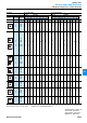
Individual Components: Type Description
Switch Bodies
+
For Front/Door Mounting
Cat. No.
Switch bodies for screw fixture
194L-E
-
Also for central fixture in conjunction with Bulletin 194L-HC actuators
For Base/DIN Rail Mounting
Switch bodies for screw fixture or
for DIN Rail (EN 50 022-35) mounting
(includes door linkage, ON-OFF switch with door interlock)
194L-A -
Rated operating current of the switching elements 12 A
16 A
20 A
25 A
12
16
20
25
Circuit diagram no.
(from pages 10-20…10-33)
xxxx
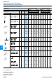
Actuators
Protection Class IP65
Cat. No.
Actuator with Central Fixture
194L-HC
-
for Bulletin 194L-E (installed with included module)
Standard Switch, Type A
Black front frame 48 x 48 mm,
black knob, silver-grey legend plate
Standard Switch, Type B
With front ring, black knob, without legend plate
Lock Actuator, Type C Control knob position:
Black front frame 48 x 48 mm,
silver-grey legend plate, RONIS lock No. 152
Lock Actuator, Type D Control knob position:
With front ring, without legend plate,
RONIS lock No. 152
4A
B
4CC
4CD
4CG
4CH
4CK
DC
DD
DG
DH
DK
001
001
001
001
001
001
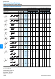
Disconnect Switch, Type E
Black front frame and knob, provision for
1 padlock, silver-grey legend plate 48 x 48 mm
4E
Disconnect Switch, Type G
Gray legend plate, black knob, provision for
3 padlocks, size 67 x 67 mm
6G
NOT-AUS, Type I
Black frame, red knob, yellow legend plate 48 x 48 mm
4I
Disconnect Switch / Emergency Stop, Type L
Black frame, red knob, provision for
1 padlock, yellow legend plate 48 x 48 mm
4L
Disconnect Switch / Emergency Stop, Type N
Yellow legend plate, red knob, provision for
3 padlocks, size 67 x 67 mm
6N
Legend Plate No. (from pages 10-20…10-33)
Actuator without legend plate
xxxz➊
001
Special Switches see pages 10-34 and 10-35
➊ The letter "z" indicates a different inscription with the same diagram (e.g. 175 I for ON/OFF
instead of 175 for 0-1)
194L-E
194L-A
D
C
B
A
I
G
N
E
L