Allen Bradley FLEX I/O Analog Modules (Cat. No.
Important User Information Because of the variety of uses for the products described in this publication, those responsible for the application and use of this control equipment must satisfy themselves that all necessary steps have been taken to assure that each application and use meets all performance and safety requirements, including any applicable laws, regulations, codes and standards. The illustrations, charts, sample programs and layout examples shown in this guide are intended solely for example.
Summary of Changes This publication contains new and revised information not included in the previous version. New Information Addition of DeviceNet Mapping A new chapter has been added to describe the special mapping for DeviceNet. Additional Flex I/O Modules New series B analog modules are now available for Flex I/O users.
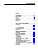
Table of Contents Summary of Changes . . . . . . . . . . . . . . . . . . . . . . . . . . . . P 1 New Information . . . . . . . . . . . . . . . . . . . . . . . . . . . . . . . . . . . . . Addition of DeviceNet Mapping . . . . . . . . . . . . . . . . . . . . . . . . Additional Flex I/O Modules . . . . . . . . . . . . . . . . . . . . . . . . . . . I/O Mapping . . . . . . . . . . . . . . . . . . . . . . . . . . . . . . . . . . . . . . Revised Information . . . . . . . . . . . . . . . . . . . . . . . . . . .
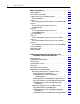
ii Table of Contents Module Programming . . . . . . . . . . . . . . . . . . . . . . . . . . . . 3-1 Chapter Objectives . . . . . . . . . . . . . . . . . . . . . . . . . . . . . . . . . . . Block Transfer Programming . . . . . . . . . . . . . . . . . . . . . . . . . . . . Sample programs for Flex I/O Analog Modules . . . . . . . . . . . . . . . PLC 3 Programming . . . . . . . . . . . . . . . . . . . . . . . . . . . . . . . . Figure 3.1 PLC 3 Family Sample Program Structure for a 1794 IE8 Module Figure 3.
Table of Contents Range Selection Bits for the 1794 OE4/B Analog Output Module (Word 5) . . . . . . . . . . . . . . . . . . . . . . . . . . . . . . Word/Bit Descriptions for the 1794 OE4/B Analog Output Module Write . . . . . . . . . . . . . . . . . . . . . . . . . . . . . . . . 4 Input/2 Output Analog Combo Module (Cat. No. 1794 IE4XOE2 Series B) . . . . . . . . . . . . . . . . . . . Analog Combo Module (1794 IE4XOE2/B) Read . . . . . . . . .
iv Table of Contents Specifications . . . . . . . . . . . . . . . . . . . . . . . . . . . . . . . . . . A-1 Differences Between Series A and Series B Analog Modules B-1 Data Table Formats . . . . . . . . . . . . . . . . . . . . . . . . . . . . . . C-1 Two's Complement Binary . . . . . . . . . . . . . . . . . . . . . . . . . . . . . . Analog Data Format . . . . . . . . . . . . . . . . . . . . . . . . . . . . . . . . . . Scaling Example . . . . . . . . . . . . . . . . . . . . . . . . . . . . . . . . . .
Preface Using This Manual Purpose of this Manual Audience This manual shows you how to use your FLEX I/O Analog modules with Allen-Bradley programmable controllers. The manual helps you install, program and troubleshoot your modules. You must be able to program and operate an Allen-Bradley programmable controller to make efficient use of your FLEX I/O modules. In particular, you must know how to program block transfers. We assume that you know how to do this in this manual.
P–2 Using This Manual Conventions We use these conventions in this manual: In this manual, we show: Like this: that there is more information about a topic in another chapter in this manual that there is more information about the topic in another manual For Additional Information For additional information on FLEX I/O systems and modules, refer to the following documents: Catalog Number Publications Voltage 1794 Description Installation Instructions 1794 FLEX I/O Product Data 1794 2.
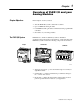
1 Chapter Overview of FLEX I/O and your Analog Modules Chapter Objectives In this chapter, we tell you about: • what the FLEX I/O system is and what it contains • types of FLEX I/O analog modules • how FLEX I/O analog modules communicate with programmable controllers • the features of your analog modules The FLEX I/O System Adapter FLEX I/O is a small, modular I/O system for distributed applications that performs all of the functions of rack-based I/O.
1–2 Overview of FLEX I/O and your Analog Modules Types of FLEX I/O Modules We describe the following FLEX I/O Analog modules in this user manual: Catalog Number Voltage Inputs Outputs Description 1794 IE8 24V dc 8 - analog - 8 input, single ended, non-isolated 1794 OE4 24V dc - 4 analog - 4 output, single ended, non-isolated 1794 IE4XOE2 24V dc 4 2 analog - 4 input, single ended, non-isolated and 2 output, single ended, non isolated FLEX I/O analog input, output and combination module
Overview of FLEX I/O and your Analog Modules 1–3 Figure 1.1 An Example of Communication Between an Adapter and an Analog Input Module 1 2 The adapter transfers your configuration data to the module using a BTW. External devices transmit analog signals to the module.
1–4 Overview of FLEX I/O and your Analog Modules Features of your Analog Modules Each module has a unique label identifying its keyswitch position, wiring and module type. A removable label provides space for writing individual designations per your application.
Chapter 2 How to Install Your Analog Module Chapter Objectives In this chapter, we tell you about: • • • • Before You Install Your Analog Module how to install your module how to set the module keyswitch how to wire the terminal base the indicators Before installing your analog module in the I/O chassis: You need to: Calculate the power requirements of all modules in each chassis.
2–2 How to Install Your Analog Module Low Voltage Directive This product is tested to meet Council Directive 73/23/EEC Low Voltage, by applying the safety requirements of EN 61131–2 Programmable Controllers, Part 2 – Equipment Requirements and Tests. For specific information required by EN 61131-2, see the appropriate sections in this publication, as well as the following Allen-Bradley publications: • Industrial Automation Wiring and Grounding Guidelines For Noise Immunity, publication 1770-4.
How to Install Your Analog Module 2–3 Methods of wiring the terminal base units are shown in the illustration below. ! ATTENTION: Do not daisy chain power or ground from an analog terminal base unit to any ac or dc discrete module terminal base unit. Analog Module Analog Module Analog Module Analog Module Daisy chaining 24V dc Note: All modules must be analog modules for this configuration.
2–4 How to Install Your Analog Module Installing the Module Installation of the analog module consists of: • mounting the terminal base unit • installing the analog module into the terminal base unit • installing the connecting wiring to the terminal base unit If you are installing your module into a terminal base unit that is already installed, proceed to “Mounting the Analog Module on the Terminal Base” on page 2–7.
How to Install Your Analog Module 2–5 5. Rotate the terminal base onto the DIN rail with the top of the rail hooked under the lip on the rear of the terminal base. Use caution to make sure that the female flexbus connector does not strike any of the pins in the mating male connector. 6. Press the terminal base down onto the DIN rail until flush. The locking tab D will snap into position and lock the terminal base to the DIN rail. 7.
2–6 How to Install Your Analog Module To install the mounting plate on a wall or panel: 1. Lay out the required points on the wall/panel as shown in the drilling dimension drawing. Drilling Dimensions for Panel/Wall Mounting of FLEX I/O Inches (Millimeters) 1.4 (35.5) 2.3 (58.5) 1.4 (35.5) 2.3 (58.5) 1.4 (35.5) .83 (21) 2. Drill the necessary holes for the #6 self-tapping mounting screws. 3.
How to Install Your Analog Module 2–7 Mounting the Analog Module on the Terminal Base Unit 1. Rotate the keyswitch (1) on the terminal base unit (2) clockwise to the position required for the specific type of analog module. 7 3 1 2 6 4 5 Analog Module Cat. No. Keyswitch Position 1794 IE8 3 1794 OE4 4 1794 IE4XOE2 5 2. Make certain the flexbus connector (3) is pushed all the way to the left to connect with the neighboring terminal base/adapter.
2–8 How to Install Your Analog Module ATTENTION: Remove field-side power before removing or inserting the module. This module is designed so you can remove and insert it under backplane power. When you remove or insert a module with field-side power applied, an electrical arc may occur.
+RZ WR ,QVWDOO
ï +RZ WR ,QVWDOO
+RZ WR ,QVWDOO
ï +RZ WR ,QVWDOO
+RZ WR ,QVWDOO
Chapter 3 Module Programming Chapter Objectives In this chapter, we tell you about: • analog data format • block transfer programming • sample programs for the PLC-3 and PLC-5 processors Block Transfer Programming Your module communicates with the processor through bidirectional block transfers. This is the sequential operation of both read and write block transfer instructions.
3–2 Module Programming Sample programs for Flex I/O Analog Modules The following sample programs show you how to use your analog module efficiently when operating with a programmable controller. These programs show you how to: • configure the module • read data from the module • update the module’s output channels (if used) These programs illustrate the minimum programming required for communication to take place.
Module Programming 3–3 Figure 3.2 PLC 3 Family Sample Program Structure for a 1794 OE4 Module Enable BTR Program Action At power up in RUN mode, or when the processor is switched from PROG to RUN, the user program enables a block transfer read. Then it initiates a block transfer write to configure the module and send data values. Thereafter, the program continuously performs read block transfers and write block transfers.
3–4 Module Programming PLC 5 Programming The PLC-5 program is very similar to the PLC-3 program with the following exceptions: • block transfer enable bits are used instead of done bits as the conditions on each rung. • separate block transfer control files are used for the block transfer instructions. Figure 3.
Module Programming 3–5 Figure 3.6 PLC 5 Family Sample Program Structure for the 1794 IE4XOE2 Program Action 1 At power up in RUN mode, or when the processor is switched from PROG to RUN, the user program enables a block transfer read. Then it initiates a block transfer write to configure the module and send data values. Thereafter, the program continuously performs read block transfers and write block transfers.
3–6 Module Programming Analog Data Format The data returned from the analog-to-digital converter in the module is 12-bit resolute. This value is left-justified into a 16-bit field, reserving the most significant bit for a sign bit.
Chapter 4 Writing Configuration to and Reading Status from Your Module with a Remote I/O Adapter Chapter Objectives In this chapter, we tell you about: • • • • Configuring Your Analog Module configuring your module’s features entering your data reading data from your module read block format Because of the many analog devices available and the wide variety of possible configurations, you must configure your module to conform to the analog device and specific application that you have chosen.
4–2 Writing Configuration to and Reading Status from Your Module with a Remote I/O Adapter Range Selection Individual input channels are configurable to operate with the following voltage or current ranges: Bit Settings 1 Ranges Configure Select Full Range 0-10V dc/0-20mA 0 1 4-20mA 1 0 10 to +10V dc 1 1 Off 0 0 When configured to Off, individual output channels will drive 0V/0mA. ! ATTENTION: If using Series A modules, do not use configure select and full range bit settings of 0.
Configuring Your Module and Reading Status from Your Module with a Remote I/O Adapter Mapping Data for the Analog Modules 4–3 The following read and write words and bit/word descriptions describe the information written to and read from the analog modules. Each word is composed of 16 bits. 8 Input Analog Module (Cat. No.
4–4 Writing Configuration to and Reading Status from Your Module with a Remote I/O Adapter Word/Bit Descriptions for the 1794-IE8 Analog Input Module Read Decimal Bit (Octal Bit) Word Read Word 0 Word 1 Word 2 Word 3 Word 4 Word 5 Word 6 Word 7 Definition Bits 00-14 (00-16) Channel 0 analog data - 12 bit left justified two's complement number; unused lower bits are zero; 4 20mA uses all 16 bits. Bits 15 (17) Channel 0 analog data sign bit.
Configuring Your Module and Reading Status from Your Module with a Remote I/O Adapter 4–5 Range Selection Bits for the 1794-IE8/B Analog Input Module Channel No.
4–6 Writing Configuration to and Reading Status from Your Module with a Remote I/O Adapter 4 Output Analog Module (Cat. No. 1794 OE4 Series B) I/O Image Input Size Module Image 0 or 1 Word Read PU Diagnostics Not used Analog Data Channel 0 Analog Data Channel 1 Analog Data Channel 2 Analog Data Channel 3 Not used Output Size Write M Full Range Config.
Configuring Your Module and Reading Status from Your Module with a Remote I/O Adapter 4–7 Analog Output Module (1794-OE4/B) Write Configuration Block Word/Dec.
4–8 Writing Configuration to and Reading Status from Your Module with a Remote I/O Adapter Word Decimal Bit (Octal Bit) Definition Word 1 Bits 00-14 (00-16) Channel 1 analog data - 12 bit left justified two's complement number; unused lower bits are zero; 4 20mA uses all 16 bits. Bits 15 (17) Channel 1 analog data sign bit. Bits 00-14 (00-16) Channel 2 analog data - 12 bit left justified two's complement number; unused lower bits are zero; 4 20mA uses all 16 bits.
Configuring Your Module and Reading Status from Your Module with a Remote I/O Adapter 4–9 4 Input/2 Output Analog Combo Module (Cat. No. 1794 IE4XOE2 Series B) Module Image I/O Image Input Data Channel 0 Input Size Input Data Channel 1 0 to 5 Words Read Input Data Channel 2 Input Data Channel 3 Underrange & Diag.
4–10 Writing Configuration to and Reading Status from Your Module with a Remote I/O Adapter Word Decimal Bit (Octal Bit) Word 3 Bits 00-14 (00-16) Channel 3 analog data - 12 bit left justified two's complement number; unused lower bits are zero; 4 20mA uses all 16 bits. Bits 15 (17) Channel 3 analog data sign bit. Bits 00-03 Underrange bits (U) for individual channels (4 20mA current inputs only) Bit 00 corresponds to input channel 0, bit 01 corresponds to input channel 1, and so on.
Configuring Your Module and Reading Status from Your Module with a Remote I/O Adapter 4–11 Range Selection Bits for the 1794-IE4XOE2/B Analog Combo Module Channel No.
4–12 Writing Configuration to and Reading Status from Your Module with a Remote I/O Adapter Word Decimal Bit (Octal Bit) Words 4 and 5 Word 6 Word 7 Chapter Summary Publication 1794 6.5.2 - May 1996 Definition Not used - set to 0. Bits 00-14 (00-16) Channel 0 Safe State analog value - 12 bit left justified two's complement number; unused lower bits are zero; 4 20mA uses all 16 bits. Bits 15 (17) Channel 0 Safe State analog data sign bit.
Chapter 5 How Communication Takes Place and I/O Image Table Mapping with the DeviceNet Adapter Chapter Objectives In this chapter you will learn about: • • • • About DeviceNet Manager DeviceNet Manager software I/O structure image table mapping factory defaults DeviceNet Manager is a software tool used to configure your FLEX I/O DeviceNet adapter and its related modules. This software tool can be connected to the adapter via the DeviceNet network.
5–2 How Communication Takes Place and I/O Image Table Mapping with the DeviceNet Adapter Adapter Input Status Word The input status word consists of: • I/O module fault bits – 1 status bit for each slot • node address changed – 1 bit • I/O status – 1 bit I/O Module Fault Bits Slot 0 1 0 Slot 1 Slot 2 Not Used Slot 3 9 8 7 6 5 4 3 2 Slot 5 Slot 4 10 through 15 Slot 6 15 Slot 7 Bit: I/O State Bit Node Address Changed Bit The adapter input status word bit descriptions are shown in the following
How Communication Takes Place and I/O Image Table Mapping with the DeviceNet Adapter Mapping Data into the Image Table 5–33 FLEX I/O analog modules are supported by the DeviceNet adapter. At present, these consist of: Module Description Catalog Number: For image table mapping refer to: 8 Input Analog Module 1794 IE8/B page 5-3 4 Output Analog Module 1794 OE4/B page 5-6 4 in/2 out Analog Combo Module 1794 IE4XOE2/B page 5-9 8 Input Analog Module (Cat. No.
5–4 How Communication Takes Place and I/O Image Table Mapping with the DeviceNet Adapter Decimal Bit 15 14 13 12 11 10 09 08 07 06 05 04 03 02 01 00 Size Octal Bit 17 16 15 14 13 12 11 10 07 06 05 04 03 02 01 00 Read Words S Analog Value Channel 7 PU Where: Not used - set to zero U7 U6 U5 Read Word 8 U4 U3 U2 U1 U0 Read Word 9 PU = Power up bit - included in series B modules only.
How Communication Takes Place and I/O Image Table Mapping with the DeviceNet Adapter Word Read Word 5 Decimal Bit Definition Bits 00-14 Channel 4 analog data - 12 bit left justified two's complement number; unused lower bits are zero; 4 20mA uses all 16 bits. Bits 15 Read Word 6 Bits 00-14 Bits 15 Read Word 7 Bits 00-14 Bits 15 Read Word 8 Bits 00-14 Bits 15 Read Word 9 5–5 Channel 4 analog data sign bit.
5–6 How Communication Takes Place and I/O Image Table Mapping with the DeviceNet Adapter 4 Output Analog Module (1794 OE4 Series B) Image Table Mapping I/O Image Input Size Read Module Image 0 or 1 Word PU Diagnostics Not used Analog Data Channel 0 Analog Data Channel 1 Analog Data Channel 2 Analog Data Channel 3 Not used Output Size Write Not used 1 to 6 Words Config.
How Communication Takes Place and I/O Image Table Mapping with the DeviceNet Adapter 5–7 Decimal Bit 15 14 13 12 11 10 09 08 07 06 05 04 03 02 01 00 Size Octal Bit 17 16 15 14 13 12 11 10 07 06 05 04 03 02 01 00 Read Words Write Words 7 thru 14 Not used - set to 0 Where: S = Sign bit (in 2's complement) OE = Output enable bits (bit 00 corresponds to output 0, bit 01 corresponds to output 1 and so on. ATTENTION: These bits must be set to 1.
5–8 How Communication Takes Place and I/O Image Table Mapping with the DeviceNet Adapter Word Decimal Bit Definition Bits 00-03 Output Enable bits. Bit 00 corresponds to input 0, bit 01 corresponds to input 1, bit 02 corresponds to input 2, and bit 03 corresponds to input 3. These bits must be set to 1. Bits 04 15 Not used - set to 0. Bits 00-03 Full range bits (F) for individual channels - Bit 00 corresponds to output channel 0, bit 01 corresponds to output channel 1, and so on.
How Communication Takes Place and I/O Image Table Mapping with the DeviceNet Adapter 5–9 Analog Combo Module (1794 IE4XOE2 Series B) Image Table Mapping Module Image I/O Image Input Data Channel 0 Input Size Read Input Data Channel 1 0 to 5 Words Input Data Channel 2 Input Data Channel 3 Underrange & Diag.
5–10 How Communication Takes Place and I/O Image Table Mapping with the DeviceNet Adapter Analog Output Module (1794-IE4XOE2/B) Write Decimal Bit 15 14 13 12 11 10 09 08 07 06 05 04 03 02 01 00 Size Octal Bit 17 16 15 14 13 12 11 10 07 06 05 04 03 02 01 00 Read Words S Analog Data - Output Channel 0 Write Word 1 S Analog Data - Output Channel 1 Write Word 2 Not used - set to 0 Not used C5 C4 C3 C2 C1 C0 0 0 F5 F4 F3 F2 OE1 OE0 Write Word 3 F1 F0
How Communication Takes Place and I/O Image Table Mapping with the DeviceNet Adapter Word Decimal Bit Underrange bits (U) for individual channels (4 20mA current inputs only) - Bit 00 corresponds to input channel 0, bit 01 corresponds to input channel 1, and so on. Bits 04 05 Wire Off bits (W) - Current outputs only - When set (1), the wire on the current output is broken or the load resistance is too high. Bit 00 corresponds to channel 0, bit 01 corresponds to channel 2, and so on.
5–12 How Communication Takes Place and I/O Image Table Mapping with the DeviceNet Adapter Defaults Each I/O module has default values associated with it. At default, each module will generate inputs/status and expect outputs/configuration.
Appendix A Specifications Specifications - 1794 IE8/B Analog Input Module Number of Inputs 8 single ended, non isolated Module Location Cat. No. 1794 TB2, TB3 Terminal Base Unit Resolution Voltage Current 12 bits unipolar; 11 bits plus sign bipolar 2.56mV/cnt unipolar; 5.13mV/cnt bipolar 5.
A–2 Specifications Specifications - 1794 IE8/B Analog Input Module General Specifications External dc Power Supply Voltage Voltage Range Supply Current Dimensions Inches (Millimeters) Environmental Conditions Operational Temperature Storage Temperature Relative Humidity Shock Vibration Conductors Operating Non operating Wire Size Category 1.8H x 3.7W x 2.1D (45.7 x 94.0 x 53.
Specifications A–3 Specifications - 1794 OE4/B Analog Output Module Number of Outputs 4 single ended, non isolated Module Location Cat. No. 1794 TB2, TB3 Terminal Base Unit Resolution Voltage Current 12 bits plus sign 2.56mV/cnt 5.13µA/cnt Data Format left justified 16 bit 2's complement Conversion Type Pulse Width Modulation Conversion Rate 1.
A–4 Specifications Specifications - 1794 OE4/B Analog Output Module General Specifications External dc Power Dimensions Supply Voltage Voltage Range Supply Current Inches (Millimeters) Environmental Conditions Operational Temperature Storage Temperature Relative Humidity Shock Vibration Conductors Operating Non operating Wire Size Category 1.8H x 3.7W x 2.1D (45.7 x 94.0 x 53.
Specifications A–5 Specifications - 1794 IE4XOE2/B 4 Input/2 Output Analog Combo Module Input Specifications Number of Inputs Resolution 4 single ended, non isolated Voltage Current 12 bits unipolar; 11 bits plus sign bipolar 2.56mV/cnt unipolar; 5.13mV/cnt bipolar 5.
A–6 Specifications Specifications - 1794 IE4XOE2/B 4 Input/2 Output Analog Combo Module Current Load on Voltage Output 3mA maximum Resistive Load on mA Output 15 750 ohms Absolute Accuracy1 Voltage Terminal Current Terminal Accuracy Drift with Temperature Voltage Terminal Current Terminal 0.133% Full Scale @ 25oC 0.425% Full Scale @ 25oC 0.0045% Full Scale/oC 0.0069% Full Scale/oC General Specifications Module Location Cat. No.
Appendix B Differences Between Series A and Series B Analog Modules The following lists major differences between series A and series B analog modules. Catalog Number 1794 IE8, 1794 OE4, 1794 IE4XOE2 Description Series A Series B Power Up bit in Read Word None This bit is set when all bits in the configuration register are 0 (unconfigured state). Change to range selection tables No off position available.
Appendix C Data Table Formats Two's Complement Binary Two’s complement binary is used when performing mathematical calculations internal to the processor. To complement a number means to change it to a negative number. For example, the following binary number is equal to decimal 22. 101102 = 2210 First, the two’s complement method places an extra bit (sign bit) in the left–most position, and lets this bit determine whether the number is positive or negative.
C–2 Data Table Formats Analog Data Format The data returned from the analog-to-digital converter in the module is 12-bit resolute. This value is left-justified into a 16-bit field, reserving the most significant bit for a sign bit.
Data Table Formats C–3 Scaling Example To scale your data to a different range: • SLC 500 – use the scaling instruction. • PLC-5 – determine a constant (slope) by dividing the desired range by the actual range. Multiply the result by your data, and add or subtract any offset. Example: A 4-20mA input places data at N13:0 (Figure 3.4 on page 3–4), with a range of 0 to 30,840. (30,840 = 7878 hex – see data format on page C–2). You want the 4-20mA (0 to 30,840) to be 32 to 1000 degrees in the PLC-5.
Index Symbols input range selection, 4-2 **Empty**, P-1, P-2, 1-1, 1-2, 2-1, 3-6, C-1 communication, between module and adapter, 1-3 Numbers 1794 IE4XOE2, specifications, 1794 IE8, specifications, C A-5 A-1 1794 OE4, specifications, A-3 A adapter input status word, 5-1 analog mapping 1794 IE8, 5-3 1794 IE4XOE2, 5-9 1794 OE4, 5-6 configuration block, block transfer write 1794 IE8/B, 4-4 1794 OE4/B, 4-7 configuring features, 4-1 connecting wiring, 2-8 1794 IE4XOE2, 2-12 1794 IE8, 2-10 1794 OE4
I–2 Index L R left justified data, 3-6, 4-2, C-2 mapping 1794 IE8, 5-3 1794 IE4XOE2, 5-9 1794 OE4, 5-6 removing and replacing, under power (RIUP), 2-8, 2-9 memory map - read 1794 IE4XOE2, 5-9 1794 IE8, 5-3 1794 OE4, 5-6 S safe state, selection of, 4-2 memory map - write 1794 IE4XOE2, 5-10 1794 IE8, 5-4 1794 OE4, 5-6 sample program, 2-7 mounting kit, cat. no.
Allen Bradley Publication Problem Report If you find a problem with our documentation, please complete and return this form.
Pub. Name FLEX I/O Analog Modules User Manual 1794 IE8, OE4, IE4XOE2 Cat. No. Series B Pub. No. Check Problem(s) Type: 1794 6.5.2 Pub. Date May 1996 Part No.
PLEASE REMOVE Other Comments PLEASE FOLD HERE NO POSTAGE NECESSARY IF MAILED IN THE UNITED STATES BUSINESS REPLY MAIL FIRST-CLASS MAIL PERMIT NO.
Support Services At Allen-Bradley, customer service means experienced representatives at Customer Support Centers in key cities throughout the world for sales service and support.
Allen Bradley, a Rockwell Automation Business, has been helping its customers improve productivity and quality for more than 90 years. We design, manufacture and support a broad range of automation products worldwide. They include logic processors, power and motion control devices, operator interfaces, sensors and a variety of software. Rockwell is one of the world's leading technology companies. Worldwide representation.