
User manual


Publication 1734-UM015A-EN-E - November 2009
Peer Data Maps 93
Peer Data Maps
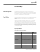
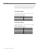
The following are data maps for each of the catalogs listed in the preceding
tables. The peer data is mapped into one of eight 24-byte memory spaces.
Peer X is the specific memory space where X is 0…7.
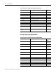
The following is a diagram to help explain the addressing of bit data and word
data in the DeviceLogix function block editor.
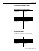
1738-IE2VM12 2-channel analog voltage input 6
1734-IT2I 2-channel, thermocouple input 8
1738-IT2IM12 2-channel, thermocouple input 8
1734-IR2 2-channel, 2-point RTD input 6
1738-IR2M12 2-channel, 2-point RTD input 6
1734-SSI Synchronous Serial Interface 10
1738-SSIM23 Synchronous Serial Interface 10
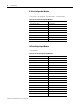
1734-232ASC RS232 ASCII Interface 4…132,
24 (default)
1738-232ASCM12 RS232 ASCII Interface 4…132,
24 (default)
1734-485ASC RS485 ASCII Interface 4…132,
24 (default)
1738-485ASCM12 RS485 ASCII Interface 4…132,
24 (default)
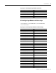
Produced I/O Sizes of Analog and Specialty Input Modules (Continued)
Catalog Number Description Produced
Size
Internal Data Table in Module
Referenced in
DeviceLogix Function Block Editor (FBE)
Peer0 Data
Peer#0 (Byte 0,Bit 0)
Peer#0 (Word 11)
Bit-addressing
Word-addressing
7 6 5 4 3 2 1 0
b7 b0
b15 b8 b7 b0
Peer1 Data
Peer2 Data
Peer3 Data
Peer4 Data
Peer5 Data
Peer6 Data
Peer7 Data
Up to 24 Bytes
Byte 0
Byte 1
Byte 2
Byte 3
Byte 4
Byte 22
Byte 23 Byte 22
Byte 23
Up to 24 Bytes
Up to 24 Bytes
Up to 24 Bytes
Up to 24 Bytes
Up to 24 Bytes
Up to 24 Bytes
Up to 24 Bytes
44954