
User manual

Publication 1734-UM015A-EN-E - November 2009
42 DeviceLogix for POINT I/O and ArmorPOINT I/O on DeviceNet
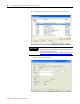
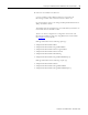
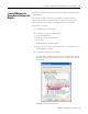
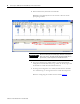
Configuration of the modules must be done through RSNetWorx for
DeviceNet. See Chapter 6
for details.
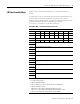
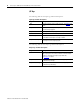
Data [34] Peer 4 - EPS (ms)
Data [35]
Data [36] Peer 5 - Slot/MacID
Data [37] Peer 5 - Consume Message Length (bytes)
Data [38] Peer 5 - EPR (ms)
Data [39]
Data [40] Peer 6 - Slot/MacID
Data [41] Peer 6 - Consume Message Length (bytes)
Data [42] Peer 6 - EPR (ms)
Data [43]
Data [44] Peer 7 - Slot/MacID
Data [45] Peer 7 - Consume Message Length (bytes)
Data [46] Peer 7 - EPR (ms)
Data [47]
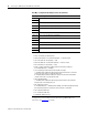
Where:
• Filter = 0 to 65535 μs (1000 = default)
• FltM = Fault Mode (0 = Use Fault Value (default), 1 = Hold Last State)
• FltV = Fault Value (0 = OFF (default), 1 = ON)
• IdlM = Idle Mode (0 = Use Idle Value (default), 1 = Hold Last State)
• IdlV = Idle Value (0 = OFF (default), 1 = ON)
• RACK = Produce with Rack Assembly 4 and Consume Rack Assembly 34
(0 = Disabled (default), 1 = Enabled)
• CFO = DeviceLogix Communication Fault Override of Outputs
1 = Enabled. When enabled, the DeviceLogix program will continue to control the
outputs even in the event of a communication fault.
0 = Disabled (default). When disabled, the outputs will follow the Fault and Idle
settings in the event of a communication fault.
• DM = Dependent Mode
1 = Enabled. When enabled, the DeviceLogix program execution will follow the
Run/Idle state of the owning processor.
• MP = Masterless Produce
0 = Disabled (default), 1 = Enabled. When enabled, the module will begin producing
data at powerup and after a connection with a controller is terminated.
• EPR = Expected Packet Rate
• PIT = Production Inhibit Time
• Slot/MacID = Address of peer
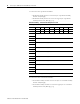
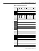
Data Map - Configuration Assembly Instance 123 (Continued)
Message Size: 48 Bytes