
User manual

Publication 1734-UM015A-EN-E - November 2009
DeviceLogix for POINT I/O and ArmorPOINT I/O on DeviceNet 39
I/O Data Assembly Maps
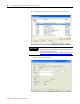
Read this section for information about how to communicate with your
module.
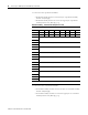
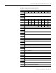
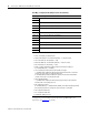
I/O messages are sent to (consumed) and received from (produced) the I/O
modules. These messages are mapped into the processor’s or scanner’s
memory. Each module produces 1, 8 or 20 bytes of input data based on which
produced assembly is selected. The default setup is 20 bytes.
It consumes 1, 8 or 20 bytes of I/O data (scanner Tx).
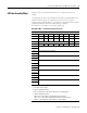
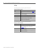
Default Data Map - Produced Assembly Instance 101
Message Size: 20 Bytes
Bit 76543210
Data [0] Pt 07 Pt 06 Pt 05 Pt 04 Pt 03 Pt 02 Pt 01 Pt 00
Data [1] PNB 07 PNB 06 PNB 05 PNB 04 PNB 03 PNB 02 PNB 01 PNB 00
Data [2] Reserved Owned LogicEn
Data [3] PM7 PM6 PM5 PM4 PM3 PM2 PM1 PM0
Data [4] Produced Network Analog Word 0
Data [5]
Data [6] Produced Network Analog Word 1
Data [7]
Data [8] Produced Network Analog Word 2
Data [9]
Data [10] Produced Network Analog Word 3
Data [11]
Data [12] Produced Network Analog Word 4
Data [13]
Data [14] Produced Network Analog Word 5
Data [15]
Data [16] Produced Network Analog Word 6
Data [17]
Data [18] Produced Network Analog Word 7
Data [19]
Where:
• Pt = value of the I/O point,
• PNB = Produced Network Bit,
• PM = Peer Missing (a 1 indicates the absence of a configured peer)
• Owned = Owned by a master.
When set to 0, the module is producing data without a master.
When set to 1, the module is producing while being owned by a master.
• LogicEn = Logic Enabled (0 = logic disabled, 1 = logic enabled)