
User manual

Publication 1734-UM015A-EN-E - November 2009
Peer Data Maps 103
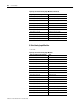
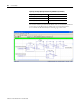
Very High Speed Counter Input Modules
This is the default map for 1734-VHSC24, 1734-VHSC5, and
1738-VHSC24M23.
Peer X (byte 4, bit 7) Channel 0 overrange
Peer X (byte 5, bit 0) Channel 1 fault
Peer X (byte 5, bit 1) Channel 1 calibration mode
Peer X (byte 5, bit 2) Channel 1 low alarm
Peer X (byte 5, bit 3) Channel 1 high alarm
Peer X (byte 5, bit 4) Channel 1 low low alarm
Peer X (byte 5, bit 5) Channel 1 high high alarm
Peer X (byte 5, bit 6) Channel 1 underrange
Peer X (byte 5, bit 7) Channel 1 overrange
Peer X (word 3) Cold junction temperature
Peer X (byte 7, bit 6) Cold junction underrange
Peer X (byte 7, bit 7) Cold junction overrange
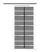
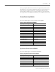
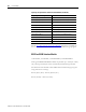
Input Tags for Very High Speed Counter Input Modules
Input Tag in DeviceLogix Editor Data
Peer X (word 0) Present data low word
Peer X (word 1) Present data high word
Peer X (word 2) Stored data low word
Peer X (word 3) Stored data high word
Peer X (byte 8, bit 1) Zero frequency detected
Peer X (byte 8, bit 2) Stored data count 2
Peer X (byte 8, bit 3) Stored data count 3
Peer X (byte 8, bit 4) A input status
Peer X (byte 8, bit 5) B input status
Peer X (byte 8, bit 6) Z input status
Peer X (byte 9, bit 0) Output 0 status
Peer X (byte 9, bit 1) Output 1 status
Peer X (byte 9, bit 2) Output 0 fault
Peer X (byte 9, bit 3) Output 1 fault
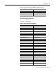
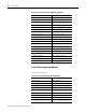
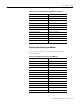
Input Tags for 2-Point Thermocouple Input Modules (Continued)
Input Tag in DeviceLogix Editor Data