POINT I/O and ArmorPOINT I/O DeviceLogix Modules User Manual (Catalog Numbers 1734-8CFGDLX, 1738-8CFGDLXM8, 1738-8CFGDLXM12, 1738-8CFGDLXM23)
Important User Information Solid state equipment has operational characteristics differing from those of electromechanical equipment. Safety Guidelines for the Application, Installation and Maintenance of Solid State Controls (publication SGI-1.1 available from your local Rockwell Automation sales office or online at http://literature.rockwellautomation.com) describes some important differences between solid state equipment and hardwired electromechanical devices.
Table of Contents Preface Purpose of This Manual. . . . . . . . . . . . . . . . . . . . . . . . . . . . . . . . . . . . . . 5 Who Should Use This Manual. . . . . . . . . . . . . . . . . . . . . . . . . . . . . . . . . 6 Related Publications . . . . . . . . . . . . . . . . . . . . . . . . . . . . . . . . . . . . . . . . . 6 Chapter 1 Introduction About This Chapter . . . . . . . . . . . . . . . . . . . . . . . . . . . . . . . . . . . . . . . . . 9 About the Modules. . . . . . . . . . . . . . . . . . . . .
2 Table of Contents Chapter 4 DeviceLogix for POINT I/O and ArmorPOINT I/O on DeviceNet About This Chapter . . . . . . . . . . . . . . . . . . . . . . . . . . . . . . . . . . . . . . . . 33 Offline Configuration using RSNetworx for DeviceNet . . . . . . . . . . . 33 Example: Build the Backplane . . . . . . . . . . . . . . . . . . . . . . . . . . . . 34 Online Configuration using RSNetWorx for DeviceNet. . . . . . . . . . . 36 I/O Data Assembly Maps . . . . . . . . . . . . . . . . . . . . . . . . . . . .
Table of Contents 3 Chapter 8 Troubleshooting About This Chapter . . . . . . . . . . . . . . . . . . . . . . . . . . . . . . . . . . . . . . . . 83 About Module Diagnostics . . . . . . . . . . . . . . . . . . . . . . . . . . . . . . . . . . 83 Status Indicators of POINT I/O Module . . . . . . . . . . . . . . . . . . . . . . 84 1734-8CFGDLX Module . . . . . . . . . . . . . . . . . . . . . . . . . . . . . . . . 84 Status Indicators of ArmorPOINT I/O Modules . . . . . . . . . . . . . . . .
4 Table of Contents Notes: Publication 1734-UM015A-EN-E - November 2009
Preface Purpose of This Manual This manual describes how to install, configure, and troubleshoot your POINT I/O DeviceLogix and ArmorPOINT I/O DeviceLogix modules. POINT I/O and ArmorPOINT I/O modules can be used in EtherNet/IP, DeviceNet, and ControlNet systems. As such, you may need to refer to other publications in addition to this one.
6 Preface Who Should Use This Manual This manual is intended for qualified personnel. You should know how to do the following: • Use RSNetWorx software or similar configuration software to set up and calibrate these modules. • Download and use electronic data sheet (EDS) files. In addition, you should be familiar with RSLogix 5000 and CIP Network terminology. If you do not, refer to your software documentation or online help before attempting to use these modules.
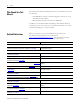
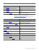
Preface Resource Description POINT I/O Voltage Terminal Module Installation Instructions, publication 1734-IN024 Provides installation information about 1734-VTM modules. POINT I/O Wiring Base Assembly Installation Instructions, publication 1734-IN511 Provides installation information about 1734-TB and 1734-TBS assemblies. POINT I/O Wiring Base Assembly Installation Instructions, publication 1734-IN013 Provides installation information about 1734-TB3 and 1734-TB3S assemblies.
8 Preface Notes: Publication 1734-UM015A-EN-E - November 2009
Chapter 1 Introduction About This Chapter This chapter introduces POINT I/O and ArmorPOINT I/O configurable modules with DeviceLogix capability. • About the Modules • Quick Start - Prepare the Modules to work on DeviceNet • Quick Start - Prepare the Modules to work on EtherNet/IP and ControlNet About the Modules The POINT I/O and ArmorPOINT I/O modules work with EtherNet/IP, DeviceNet and ControlNet network adapters. Each module has eight 24V DC I/O points that self-configure to be inputs or outputs.
10 Introduction 1734-8CFGDLX This module is an 8-point 24V DC I/O module with 8 self-configuring points and DeviceLogix capabilities. Each of the I/O points can be either a DC input or output. The module supports removal and insertion under power, auto-address, and auto-baud in compliance with the POINTBus backplane. 1738-8CFGDLXM8, 1738-8CFGDLXM12, and 1738-8CFGDLXM23 The ArmorPOINT I/O family consists of modular I/O modules. The sealed IP67 housing of these modules requires no enclosure.
Introduction 11 Stand Alone DeviceLogix If DeviceLogix is enabled (programmed), then the module becomes the owner of its outputs. The DeviceLogix program reads inputs and controls the onboard outputs. • The produced assembly may be shared with a controller if a connection exists. • As the owner of its local outputs, the module may run without an external controller.
12 Introduction Quick Start - Prepare the Modules to work on DeviceNet Mount the Module For POINT I/O, see Chapter 2. For ArmorPOINT I/O, see Chapter 3. Wire the Module For POINT I/O, see Chapter 2. For ArmorPOINT I/O, see Chapter 3. Configure DeviceNet Network and Scanner See Chapter 4. Configure the Module using RSNetWorx for DeviceNet See Chapter 6. Write the DeviceLogix Program See Chapter 7.
Introduction Quick Start - Prepare the Modules to work on EtherNet/IP and ControlNet 13 Mount the Module For POINT I/O, see Chapter 2. For ArmorPOINT I/O, see Chapter 3. Wire the Module For POINT I/O, see Chapter 2. For ArmorPOINT I/O, see Chapter 3. Add Module to RSLogix 5000 See Chapter 5. Write the DeviceLogix Program in RSNetworx for DeviceNet See Chapter 7.
14 Introduction Notes: Publication 1734-UM015A-EN-E - November 2009
Chapter 2 Install POINT I/O DeviceLogix Modules If you are using ArmorPOINT I/O modules (1738-8CFGDLXM8/M12/M23), go to Chapter 3, Install ArmorPOINT I/O DeviceLogix Modules.
16 Install POINT I/O DeviceLogix Modules ATTENTION WARNING ATTENTION POINT I/O is grounded through the DIN rail to chassis ground. Use zinc-plated, yellow-chromated steel DIN rail to assure proper grounding. The use of DIN rail materials (for example, aluminum or plastic) that can corrode, oxidize, or are poor conductors, can result in improper or intermittent grounding. Secure DIN rail to mounting surface approximately every 200 mm (7.8 in.).
Install POINT I/O DeviceLogix Modules Install the Mounting Base Assembly 17 The 1734-8CFGDLX is compatible with 1734-TB, 1734-TBS, 1734-TOP, and 1734-TOPS wiring bases. The 1734-TB or 1734-TBS wiring base assembly consists of a 1734-MB mounting base and a 1734-RTB or 1734-RTBS removable terminal block (RTB).
18 Install POINT I/O DeviceLogix Modules To install the mounting base assembly on the DIN rail, proceed as follows. 1. If you are using the 1734-TB or 1734-TBS mounting base, attach the RTB to the mounting base. Otherwise, skip to step 2. Removable Terminal Block (RTB) Mounting Base 44858 2. Position the mounting base (wiring base assembly) vertically above the installed units, for example, adapter, power supply, or existing module. 3.
Install POINT I/O DeviceLogix Modules Install an I/O Module 19 Install the module before or after base installation. Make sure that the mounting base is correctly keyed before installing the module into the mounting base. In addition, make sure the mounting base locking screw is positioned horizontally referenced to the base. WARNING When you insert or remove the module while backplane power is on, an electrical arc can occur. This could cause an explosion in hazardous location installations.
20 Install POINT I/O DeviceLogix Modules M St od at u us le 3 1 O 73 B 4 4E 2 1 0 2 S 4V O ou DC ut rc pu e t N S e N ta tw O t o D us rk E: 3. Insert the module straight down into the mounting base and press to secure. 44967 4. Secure the module with the RTB removal handle (for 1734-TB or 1734-TBS bases) or handle (for 1734-TOP or 1734-TOPS bases).
Install POINT I/O DeviceLogix Modules Install the Removable Terminal Block 21 A removable terminal block (RTB) is supplied with your mounting base assembly. To remove, pull up on the RTB handle. This lets you remove and replace the base when necessary without removing any of the wiring. To re-insert the RTB, proceed as follows. WARNING When you connect or disconnect the RTB with field-side power applied, an electrical arc can occur. This could cause an explosion in hazardous location installations.
22 Install POINT I/O DeviceLogix Modules Remove a 1734-TB or 1734-TBS Base To remove a 1734-TB or 1734-TBS mounting base, do the following. WARNING When you insert or remove the module while backplane power is on, an electrical arc can occur. This could cause an explosion in hazardous location installations. Be sure to remove power or that the area is nonhazardous before proceeding. 1. Unlatch the RTB handle on the I/O module. 2. Pull on the RTB handle to remove the RTB. 3.
Install POINT I/O DeviceLogix Modules Remove a 1734-TOP or 1734-TOPS Base 23 To remove a wiring base from the DIN rail, you must remove the module installed to the right of the base. WARNING If you connect or disconnect wiring while the field-side power is on, an electrical arc can occur. This could cause an explosion in hazardous location installations. Be sure that power is removed or the area is nonhazardous before proceeding. 1.
24 Install POINT I/O DeviceLogix Modules Wire the Modules This section provides wiring instructions for the modules.
Install POINT I/O DeviceLogix Modules Channel 25 Terminal Number I/O Common Voltage 0 0 External(1) External(2) 1 1 2 2 3 3 4 4 5 5 6 6 7 7 10/28.8 V DC is supplied through the internal power bus. (1) Common connections require an external connection, such as a 1734-CTM module. (2) Supply Voltage Connections require an external connection such as a 1734-VTM module. System and Power Considerations There are no power terminals on the POINT I/O DeviceLogix module.
26 Install POINT I/O DeviceLogix Modules Example of Logical Partitioning ADN Adapter Status DeviceNet Status PointBus Status 1734-ADN I E 2 C EP24DC O E 2 C I B 2 O B 2 E I B 2 1734-EP24DC System Power Status Power O B 4 E O B 2 E r DeviceNet Power DeviceNet Power 0 1 0 1 0 1 0 1 0 1 0 1 0 1 0 1 1 12V DC supply 24V DC supply 1734adn4 Similarly, field power and common (return) can be terminated in the POINT I/O system by using the following modules: • 1734-VTM (Voltage termination
Chapter 3 Install ArmorPOINT I/O DeviceLogix Modules If you are using POINT I/O modules (1734-8CFGDLX), go to Chapter 2, Install POINT I/O DeviceLogix Modules.
28 Install ArmorPOINT I/O DeviceLogix Modules Mounting illustration for the ArmorPOINT adapter with I/O bases Adapter Adapter 47.2 mm 1.9 in 47.2 mm 1.9 in 50 mm 2.0 in 50 mm 2.0 in 50 mm 2.0 in 22 mm 0.87 in 22 mm 0.87 in 22 mm 0.87 in 50 mm 2.0 in 22 mm 0.87 in 50 mm 2.0 in 50 mm 2.0 in 102 mm 102 4.02 in mm 4.02 in 46 mm 1.81 in 46 mm 1.81 in 43769 Install the mounting as follows: 1. Lay out the required points as shown above in the drilling dimension drawing. 2.
Install ArmorPOINT I/O DeviceLogix Modules Install the Module 29 Follow the instructions to install the module. 1. Using a bladed screwdriver, rotate the keyswitch on the mounting base clockwise until the number 1 aligns with the notch in the base. Keyswitch Set to position 1, for the 1738 24V DC modules 43675 2. Position the module vertically above the mounting base. The module bridges two bases.
30 Install ArmorPOINT I/O DeviceLogix Modules Remove the Module from the Mounting Base Follow the instructions to remove the module from the mounting base. 1. Put a flat blade screwdriver into the slot of the orange latching mechanism. 2. Push the screwdriver toward the I/O module to disengage the latch. The module lifts up off the base. 3. Pull the module off the base. Wire the Modules This section provides wiring instructions for the modules.
Install ArmorPOINT I/O DeviceLogix Modules 31 1738-8CFGDLXM8 Wiring Diagram 43583 (view into connector) Pin 1 - 24V DC Pin 3 - Common Pin 4 - I/O 0 (M8-A) I/O 1 (M8-B) I/O 2 (M8-C) I/O 3 (M8-D) I/O 4 (M8-E) I/O 5 (M8-F) I/O 6 (M8-G) I/O 7 (M8-H) 1738-8CFGDLXM12 I/O Module H A Connectors M12-E...H Connectors M12-A...
32 Install ArmorPOINT I/O DeviceLogix Modules 1738-8CFGDLXM23 I/O Module 1738-8CFGDLXM23 24V DC In M23 connector MOD NET DLX 0 1 2 LED indicators 3 4 5 6 7 44353 1738-8CFGDLXM23 Wiring Diagram 43681 (view into connector) Pin 1 - I/O 0 Pin 2 - I/O 1 Pin 3 - I/O 2 Pin 4 - I/O 3 Pin 5 - I/O 4 Pin 6 - I/O 5 Pin 7 - I/O 6 Pin 8 - I/O 7 Pin 9 - Return (Com) Pin 10 - Return (Com) Pin 11 - 24V DC Pin 12 - Chassis The ArmorPOINT I/O DeviceLogix module gets its power from the Field Power Bus of the backp
Chapter 4 DeviceLogix for POINT I/O and ArmorPOINT I/O on DeviceNet About This Chapter This chapter provides information on the following: • Offline Configuration using RSNetworx for DeviceNet • Online Configuration using RSNetWorx for DeviceNet • I/O Data Assembly Maps Offline Configuration using RSNetworx for DeviceNet This section is not a substitute for RSNetworx or DeviceNet scanner and adapter publications.
34 DeviceLogix for POINT I/O and ArmorPOINT I/O on DeviceNet Example: Build the Backplane This example shows you how to build the backplane. The following screen shows the 1734-ADN Point I/O Scanner added. Next, locate the I/O modules. In this example, the following modules will be added: • 1734-8CFGDLX POINT I/O DeviceLogix module • 1734-IB8 POINT I/O DC Input module • 1734-IE4C POINT I/O 4...
DeviceLogix for POINT I/O and ArmorPOINT I/O on DeviceNet 35 The digital modules can be found under the category, “General Purpose Discrete I/O”, and the analog modules can be found under the “Rockwell Automation miscellaneous” category. The configuration of each module can now be edited from the Properties dialog box of each module. For instructions on editing the configuration of the DeviceLogix module, see Chapter 6. Include all the I/O modules in the backplane to the Scanner’s scan list.
36 DeviceLogix for POINT I/O and ArmorPOINT I/O on DeviceNet Online Configuration using RSNetWorx for DeviceNet To set up a DeviceNet network using RSNetWorx for DeviceNet when connected to the network, do the following: 1. If you have a DNT file that has been configured, open the file in RSNetWorx for DeviceNet. To do this, go to the Online mode by pressing . You can also click Network > Online, or click the Online button . RSLinx will start.
DeviceLogix for POINT I/O and ArmorPOINT I/O on DeviceNet 37 To update all the modules in the most efficient way, click Network > Download to Network on the menu bar. 5. Review the Message window for any errors. The stored configuration (DNT file) and the configuration of all the modules now match. 6. If any changes are made, be sure to download them to the module and save them in the DNT file. 7. When in the Online mode, you can change the configuration of a module by double-clicking its icon.
38 DeviceLogix for POINT I/O and ArmorPOINT I/O on DeviceNet Familiarize yourself with all the tabs in the Properties window before proceeding to Chapter 6 where you will learn how to configure the DeviceLogix module.
DeviceLogix for POINT I/O and ArmorPOINT I/O on DeviceNet I/O Data Assembly Maps 39 Read this section for information about how to communicate with your module. I/O messages are sent to (consumed) and received from (produced) the I/O modules. These messages are mapped into the processor’s or scanner’s memory. Each module produces 1, 8 or 20 bytes of input data based on which produced assembly is selected. The default setup is 20 bytes. It consumes 1, 8 or 20 bytes of I/O data (scanner Tx).
40 DeviceLogix for POINT I/O and ArmorPOINT I/O on DeviceNet You can select other produced assemblies: • Produced assembly instance 4 is the first byte of produced assembly instance 101 (Data [0]). • Produced assembly instance 111 is the first eight bytes of produced assembly instance 101 (Data [0]…[7]).
DeviceLogix for POINT I/O and ArmorPOINT I/O on DeviceNet 41 Data Map - Configuration Assembly Instance 123 Message Size: 48 Bytes Bit 7 6 5 Data [0] Group Off2On Input filter 4 3 2 1 0 Data [1] Data [2] Group On2Off Input filter Data [3] Data [4] FltM 7 FltM 6 FltM 5 FltM 4 FltM 3 FltM 2 FltM 1 FltM 0 Data [5] FltV 7 FltV 6 FltV 5 FltV 4 FltV 3 FltV 2 FltV 1 FltV 0 Data [6] IdlM 7 IdlM 6 IdlM 5 IdlM 4 IdlM 3 IdlM 2 IdlM 1 IdlM 0 Data [7] IdlV 7 IdlV 6 IdlV 5 Id
42 DeviceLogix for POINT I/O and ArmorPOINT I/O on DeviceNet Data Map - Configuration Assembly Instance 123 (Continued) Message Size: 48 Bytes Data [34] Peer 4 - EPS (ms) Data [35] Data [36] Peer 5 - Slot/MacID Data [37] Peer 5 - Consume Message Length (bytes) Data [38] Peer 5 - EPR (ms) Data [39] Data [40] Peer 6 - Slot/MacID Data [41] Peer 6 - Consume Message Length (bytes) Data [42] Peer 6 - EPR (ms) Data [43] Data [44] Peer 7 - Slot/MacID Data [45] Peer 7 - Consume Message Length (bytes) Data [46] Pee
Chapter 5 DeviceLogix for POINT I/O and ArmorPOINT I/O on Ethernet/ControlNet About This Chapter In this chapter, you will learn how to perform the following tasks: • Create a POINT I/O DeviceLogix module in RSLogix 5000 when using EtherNet/IP or ControlNet adapters • Identify the tags created in your program for your use • Use RSNetworx for DeviceNet to configure the POINT I/O DeviceLogix module Add a POINT I/O DeviceLogix Module to RSLogix 5000 To add a POINT I/O DeviceLogix module to RSLogix 5000,
44 DeviceLogix for POINT I/O and ArmorPOINT I/O on Ethernet/ControlNet 3. Under Digital, double-click the Point I/O DeviceLogix module. IMPORTANT If you cannot find the module in the Select Module dialog box, you will need to install the Add-On Profile (AOP) for the module. You can download the AOP from http://www.rockwellautomation.com/support/downloads.html. The following dialog box appears.
DeviceLogix for POINT I/O and ArmorPOINT I/O on Ethernet/ControlNet 45 4. Enter the slot number in the Slot box. It is not possible to make a Rack connection to the Point I/O DeviceLogix module. The connection must be a direct one. On the Connection tab, you can change the Requested Packet Interval (RPI), the default is 20 ms. The Module Info tab will display the status and identity information of the module when the module is online. There is no tab for configuration.
46 DeviceLogix for POINT I/O and ArmorPOINT I/O on Ethernet/ControlNet I/O Tags The following table lists the input tags and their descriptions. Input tags and their descriptions Tag Description Data This will contain the state of eight I/O points. See Chapter 6 for details. LogicDefinedData These eight bits are assigned using the Network Output Bit tags in the DeviceLogix program. LogicEnabled When set, the DeviceLogix program is running. Owned When set, the module is owned by a master.
DeviceLogix for POINT I/O and ArmorPOINT I/O on Ethernet/ControlNet Launch RSNetworx for DeviceNet to Configure the Module 47 The Point I/O DeviceLogix module can only be configured using RSNetWorx for DeviceNet. The following example assumes that the module is configured while it is online. If the module is configured offline, then apply the same procedure when you download the contents of the DNT file to the I/O module. To configure the module: 1. Start RSNetworx for DeviceNet. 2.
48 DeviceLogix for POINT I/O and ArmorPOINT I/O on Ethernet/ControlNet 5. Select Pointbus Port, DeviceNet and click OK. RSNetWorx automatically browses the network to discover all the participating modules. IMPORTANT Note the online path in the Messages window at the bottom half of the screen. This path will be saved in the DNT file. To open the file, select Properties on the Network menu. 6.
Chapter 6 Configuring POINT I/O and ArmorPOINT I/O DeviceLogix modules using RSNetworx for DeviceNet About This Chapter In this chapter, you will learn how to do the following: • • • • • Configure the Module using the Configuration tab 49 Configure the module using the Configuration tab Use the data on the Parameters tab Configure peer communication Produce data without using a master Start the DeviceLogix Function Block Editor on the DeviceLogix tab The following diagram shows the Configuration tab
50 Configuring POINT I/O and ArmorPOINT I/O DeviceLogix modules using RSNetworx for DeviceNet Parameters on the Configuration tab Parameter Description Off-to-On Delay This is the OFF to ON filter constant for all inputs on the module. A high signal must be present for this amount of time before the module will report an ON. The value must be entered in microseconds (μs). The default value is 1000 μs. The minimum value is 0 and the maximum is 65535 μs.
Configuring POINT I/O and ArmorPOINT I/O DeviceLogix modules using RSNetworx for DeviceNet 51 Parameters on the Configuration tab (Continued) Parameter Description DLX Dependent Mode This parameter allows the logic in the module to be enabled or disabled according to the I/O connection status or the state of the owning processor. The default is disabled. If Dependent Mode is enabled, the DeviceLogix program will be disabled when the owning processor is in program mode.
52 Configuring POINT I/O and ArmorPOINT I/O DeviceLogix modules using RSNetworx for DeviceNet Parameters on the Configuration tab (Continued) Parameter Description Peer #xx MacID There are eight (0…7) peer Mac ID parameters. Each one defines the MacID or Slot Number of the peer from which this module will consume data. The default is "No Connection." You can enter the MacID or Slot number, 0…63, or a relative offset from the address of the module (-4 to +4).
Configuring POINT I/O and ArmorPOINT I/O DeviceLogix modules using RSNetworx for DeviceNet 53 Parameters on the Parameters tab Parameters on the Parameters tab Parameter Description Data Input/Output This parameter is the same as the first byte of the Produced I/O assembly. It is the state of the eight I/O points. Data - Consumed Bits This parameter is the same as the second byte of the Consumed I/O assembly. It is the state of the Consumed Network Bits or User Defined Bit Data.
54 Configuring POINT I/O and ArmorPOINT I/O DeviceLogix modules using RSNetworx for DeviceNet Parameters on the Parameters tab (Continued) Configure Peer Communication Parameter Description Zone Control This is a legacy parameter for DeviceLogix and ZIP. It shows the state of Zone Control, whether it is enabled or disabled. Sequential Auto Address This parameter should only be used in a DeviceNet system.
Configuring POINT I/O and ArmorPOINT I/O DeviceLogix modules using RSNetworx for DeviceNet 55 • Consume data from a safety connection The module can consume data from a safety module with a standard connection. • Consume data sent to a peer from a master. Set Up Peer Communication Parameters For each peer, you need to configure a set of parameters. Here are the three parameters in their default settings (no peer data).
56 Configuring POINT I/O and ArmorPOINT I/O DeviceLogix modules using RSNetworx for DeviceNet Select bit0 of byte0. With up to 24 bytes of data available for mapping, the last entry is "Peer#0 (Byte 23, Bit7)." 192 bits per peer can be used for a total of 1536 data bits. You are highly encouraged to use the connection status bits to verify that the device is receiving valid data from the peer. They are located under the Status Input category of the "bit input" I/O tags.
Configuring POINT I/O and ArmorPOINT I/O DeviceLogix modules using RSNetworx for DeviceNet 57 The 1734-IE4C has an input message that looks like this: Default Data Map for the 1734-IE4C Analog Input Module Message size: 12 bytes Byte 15 14 13 12 11 10 09 08 07 06 05 04 03 02 01 00 Produces (scanner Rx) Input Channel 0 High Byte Input Channel 0 Low Byte Input Channel 1 High Byte Input Channel 1 Low Byte Input Channel 2 High Byte Input Channel 2 Low Byte Input Channel 3 High Byte Input Channel 3 L
58 Configuring POINT I/O and ArmorPOINT I/O DeviceLogix modules using RSNetworx for DeviceNet If the POINT I/O DeviceLogix module is consuming data from a peer that has double precision analog data (32-bit), like the 1734-VHSC24, the data can be used in logic by addressing the high-word and low-word separately. By using math functions (multiply and add), the two words can be combined into one value. See Very High Speed Counter Input Modules in Appendix A.
Configuring POINT I/O and ArmorPOINT I/O DeviceLogix modules using RSNetworx for DeviceNet 59 Due to the fact that there is no master to verify the connection and the configuration of each module, it is recommended that the ZIP Security Key be produced in the data. This unique number is calculated using the identity of the module and the present configuration. The ZIP Security Key value is in the DeviceLogix Logic Editor, under the Analog Input I/O tags.
60 Configuring POINT I/O and ArmorPOINT I/O DeviceLogix modules using RSNetworx for DeviceNet In this example, the ZIP Security Key is mapped to Network Output Word 3. Any module receiving this data should verify the constant value. For example: The ZIP Security Key constant is added using the ellipses button of the NEQ function block. This output can be used to condition the execution of other function blocks using the Enable input.
Configuring POINT I/O and ArmorPOINT I/O DeviceLogix modules using RSNetworx for DeviceNet Start the Function Block Editor 61 To start the Function Block editor, do the following. 1. Go to the property dialog box of the module. 2. Click the DeviceLogix tab, followed by Start Logic Editor. On this tab, you can enter the Author’s name, revision, and description of the logic program. These are generic text fields. They are saved in the DNT file created by the RSNetworx for DeviceNet application.
62 Configuring POINT I/O and ArmorPOINT I/O DeviceLogix modules using RSNetworx for DeviceNet If a program is saved in the DNT file, it will be displayed. To learn how to use this editor, refer to Chapter 2 of the DeviceLogix System User Manual, publication RA-UM003. For specific uses of the POINT I/O and ArmorPoint I/O DeviceLogix modules, proceed to Chapter 7.
Chapter 7 DeviceLogix Capabilities About This Chapter This chapter lists the DeviceLogix capabilities supported by the POINT I/O DeviceLogix and ArmorPOINT I/O DeviceLogix modules. Function Block Instructions The module can support up to 144 function blocks.
64 DeviceLogix Capabilities Timing Diagnosis The DeviceLogix Timing Diagnosis function block object determines whether the occurrence of the expected event is within the preset timing interval. For more information on the Alarm and Timing Diagnosis function blocks, refer to the DeviceLogix System User Manual, publication RA-UM003. Filter Category The Filter category includes a single instruction type: Low Pass Filter.
DeviceLogix Capabilities 65 High/Low Limit The DeviceLogix High/Low Limit function block limits the input value within the specified data range. The High/Low Limit function block is outlined in detail as follows. IF value of Input > HighLimit Output = HighLimit ELSE IF value of Input < LowLimit Output = LowLimit ELSE Output = Input END For more information on the Select and High/Low Limit function block, refer to the DeviceLogix System User Manual, publication RA-UM003.
66 DeviceLogix Capabilities For more information on the Timer/Counter category, refer to the DeviceLogix System User Manual, publication RA-UM003.
DeviceLogix Capabilities 67 Output is Clear END For more information on the Comparison category, refer to the DeviceLogix System User Manual, publication RA-UM003.
68 DeviceLogix Capabilities For more information on the Compute category, refer to the DeviceLogix System User Manual, publication RA-UM003. Move/Logical Category The Move/Logical category includes fundamental bit type logic operations, including the instruction types: • Boolean • AND (BAND) • Not AND (BNAND) • OR (BOR) • Not OR (BNOR) • Exclusive OR (BXOR) • Exclusive Not OR (BXNOR) • NOT (BNOT) • Latch • Set Latch (SETD) • Reset Latch (RESD) Boolean Functions The Boolean functions are as follows.
DeviceLogix Capabilities Function Block Type Input 1 Input 2 Output Value Not OR (BNOR) 0 0 1 0 1 0 1 0 0 1 1 0 0 0 0 0 1 1 1 0 1 1 1 0 0 0 1 0 1 0 1 0 0 1 1 1 0 N/A 1 1 N/A 0 Exclusive OR (BXOR) Exclusive Not OR (BXNOR) NOT (BNOT) (1) (1) 69 The Input number can be set in a property page; the default number is 2. BNOT has only one input. Latch Functions There are two kinds of Latch functions: Set Dominant Latch (SR) and Reset Dominant Latch (RS).
70 DeviceLogix Capabilities Function Block Type Reset Set Value at time + Value at time + t0 t0+1 RS (Reset Dominant) 0 0 0 0 0 1 0 1 1 0 0 0 1 1 0 0 0 0 1 1 0 1 1 1 1 0 1 0 1 1 1 0 For more information on the Move/Logical category, refer to the DeviceLogix System User Manual, publication RA-UM003. Logic Execution Time The execution time is dependent on the total number of function blocks used in the entire DeviceLogix program.
DeviceLogix Capabilities 71 Digital Inputs to Function Blocks When the Bit Input I/O tag connector is added to the DeviceLogix editor, the following input options are available: Hardware Discrete Input 0 through Discrete Input 7 are the states of the eight I/O points on the module. Status The following is a list of status bits that can be selected.
72 DeviceLogix Capabilities If you are using the EtherNet/IP or ControlNet adapter, it is suggested that you use the COS/Cyclic connection status bits to determine the health of the connection with a master. The following are the status bits for the eight Peer connections: • Peer#X Data valid • Peer#X Exists Use the Exists bits to determine if a connection is configured, and the Data Valid bit to check if the data from the peer has been received in the expected time (EPR) and with the expected data size.
DeviceLogix Capabilities 73 Analog Inputs to Function Blocks When the Analog Input I/O tag connector is added to the DeviceLogix editor, the following options are available. Network Analog Input Network Input Word 0 through Network Input Word 7 are sent to the DeviceLogix program through the Output Assembly. In RSLogix500, the tag name for these words is UserDefinedWordData[0..7].
74 DeviceLogix Capabilities Digital Outputs from Function Blocks Hardware Discrete Output 0 through Discrete Output 7 are the eight hardware outputs available on the module. If these tags are unused (that is, not mapped in the DeviceLogix program), then there is a virtual mapping from the Data Byte Output Assembly to the output point. This means that the output is under control of the owning processor. If the Discrete Output is mapped in logic, it is controlled by the module.
DeviceLogix Capabilities 75 This flowchart shows the process and priority the module follows when updating each Digital Output Point (DOP). The process considers module states such as Network Fault and Run/Idle, configurable parameters such as Network Fault Override, and Logic states such as Logic Enabled and Force.
76 DeviceLogix Capabilities Network Network Output Bit 0 through Network Output Bit 7 are mapped to the Input I/O Assembly byte 1. These bits can be sent to the owning processor or to other peers. In RSLogix 5000, the tag name is UserDefinedBitData. Analog Outputs from Function Blocks Network Network Output Word 0 through Network Output Word 7 are mapped to the Input I/O Assembly. These words can be sent to the owning processor or to other peers. In RSLogix 5000, the tag name is UserDefinedWordData[0..
DeviceLogix Capabilities Enable Line feature 77 The Enable Line feature can be supported by each instruction type in the Function Block Editor. When an instruction supports the Enable Line feature, that particular instruction can only be executed when Enable Line is on; otherwise, that instruction maintains the data from the last data scan. In this manner, functions can be executed conditionally based on the state of the Enable input.
78 DeviceLogix Capabilities Offline and Online Editing Editing of the configuration and DeviceLogix program can be done off-line and saved in the DNT file created by RSnetWorx for DeviceNet. The changes, however, must be manually downloaded to the module while online. When using RSLogix 5000 with an EtherNet/IP or ControlNet adapter, the forward open to the DeviceLogix module does not contain any configuration information. The configuration must be sent via RSNetWorx for DeviceNet while online.
DeviceLogix Capabilities Enable/Disable Logic 79 For logic to execute, it must be enabled. While editing online with RSNetWorx for DeviceNet, you can enable logic. Logic Enable On Use the Logic Enable On function to notify the device to start processing the stored logic diagram. To set Logic Enable On, select Communications > Logic Enable On. Logic Enable Off Use the Logic Enable Off option to notify the device to stop executing the logic program.
80 DeviceLogix Capabilities Messaging There are certain parameters that you may want to SET or READ from the module that are not part of the I/O Assemblies. Those parameters are still available through messaging. This section contains advanced user information. You should understand the CIP object model and be familiar with the terms Service, Class, Instance, and Attribute.
DeviceLogix Capabilities 81 The following table shows this data for the Logic Supervisor, Timer, and Counter function blocks.
82 DeviceLogix Capabilities To configure the message, do the following: 1. Click the ellipsis (…) button. The Message Configuration dialog box appears. 2. Set the message type to “CIP Generic.” 3. Set the Service Type to “Set Attribute Single” to set data or “Get Attribute Single” to read data. 4. Enter the Class value in hexadecimal from the table (“30A” is the Timer function block). 5. Copy the Instance number from the upper left corner of the Timer function block to which you are sending the message.
Chapter 8 Troubleshooting About This Chapter This chapter provides information about module diagnostics, and about troubleshooting with the following indicators: • • • • • Module status Network status DeviceLogix status Power indication I/O POINT status (ON/OFF/fault or diagnostic) In addition, the following troubleshooting scenarios are provided: • Peer connection is not working • Configuration or DeviceLogix program cannot be downloaded to the module • Module’s DeviceLogix program exits the Run mode
84 Troubleshooting Status Indicators of POINT I/O Module See the figure and tables that show how to interpret the status indicators.
Troubleshooting 85 Network Status Indication Probable Cause Recommended Action Off Device is not online. - Device has not completed dup_MAC_id test. - Device not powered - check module status indicator. Apply power to device, wait for dup_MAC_id to complete, and correct, as needed. Green Device is online and has connections in the established state. None. Flashing green Device is online but has no connections in the established state. None .
86 Troubleshooting Status Indicators of ArmorPOINT I/O Modules See the figure and tables that show how to interpret the status indicators.
Troubleshooting 87 Network Status Indication Description Recommended action Off Device is not online: - Device has not completed dup_MAC-id test. - Device not powered – check module status indicator. Apply power to device, wait for MAC_id to complete, and correct, as needed. Green Device is online and has one or more I/O connections in established state. None. Flashing green Device is online but has no connections in established state. None.
88 Troubleshooting Troubleshooting Scenarios The following are scenarios you may encounter while using the modules. Peer connection is not working If the Network Status LED is flashing red, one or more connections to the device are broken or not functioning properly. If the device has been configured to consume data from peers, it is possible that the data size or data rate have not been configured correctly. • Use the Peer Missing bits in the I/O assembly to check which peer connection is missing.
Troubleshooting 89 Configuration or DeviceLogix program cannot be downloaded to the module A DeviceLogix program and most configurable parameters cannot be changed while the DeviceLogix program is running or when an I/O connection is active. • Inhibit the connection in RSLogix 5000 (if using EtherNet/IP and ControlNet). • Disable logic in RSNetWorx for DeviceNet before downloading.
90 Troubleshooting • Clear the Node Active check box in RSNetWorx for DeviceNet (if using a DeviceNet scanner or DeviceNet adapter). Module’s DeviceLogix program exits the Run mode unexpectedly The module’s DeviceLogix program exits the Run mode unexpectedly. A possible reason may be that the ADR feature of the scanner is turned on and the ADR data of the module stored in the scanner is not consistent with what is on the module.
Appendix A Peer Data Maps About This Appendix This appendix contains information to help you use peer data from POINT I/O and ArmorPOINT I/O modules in your DeviceLogix program. For descriptions or details on the individual modules, refer to the Installation Instructions or User Manual for the specific modules. Peer I/O Sizes The following tables list the produced I/O sizes of the digital and analog input modules, including those of the POINT I/O and ArmorPOINT I/O modules.
92 Peer Data Maps Produced I/O Sizes of Digital Input Modules (Continued) Catalog Number Description Produced Size 1734-IA2 2-channel 120V AC input 1 1738-IA2M12AC3 2-channel 120V AC input 1 1738-IA2M12AC4 2-channel 120V AC input 1 1734-IA4 4-channel 120V AC input 1 1734-IM2 2-channel 220V AC input 1 1734-IM4 4-channel 220V AC input 1 1734-IB16DM12 16-point sinking DC input with diagnostics 2 (default), 3 1734-8CFG 8-point DC input/output 1 1738-8CFGM12 (M8, M23) 8-point DC inpu
Peer Data Maps 93 Produced I/O Sizes of Analog and Specialty Input Modules (Continued) Peer Data Maps Catalog Number Description Produced Size 1738-IE2VM12 2-channel analog voltage input 6 1734-IT2I 2-channel, thermocouple input 8 1738-IT2IM12 2-channel, thermocouple input 8 1734-IR2 2-channel, 2-point RTD input 6 1738-IR2M12 2-channel, 2-point RTD input 6 1734-SSI Synchronous Serial Interface 10 1738-SSIM23 Synchronous Serial Interface 10 1734-232ASC RS232 ASCII Interface 4…13
94 Peer Data Maps In the following sections, the input tag name in the DeviceLogix editor is given in the left column, and a description of the tag is given in the right column. This section is intended to be used as a quick guide. For details, refer to the installation instructions or user manual for the specific peer module.
Peer Data Maps 95 4-Point Digital Input with Diagnostics Modules 1734-IB4D, 1738-IB4DM12 Input Tags for 4-Point Digital Input with Diagnostic Modules Input Tag in DeviceLogix Editor Data Peer X (byte 0, bit 0) Input channel 0 Peer X (byte 0, bit 1) Input channel 1 Peer X (byte 0, bit 2) Input channel 2 Peer X (byte 0, bit 3) Input channel 3 Peer X (byte 0, bit 4) Fault channel 0 Peer X (byte 0, bit 5) Fault channel 1 Peer X (byte 0, bit 6) Fault channel 2 Peer X (byte 0, bit 7) Fault chan
96 Peer Data Maps 8-Point Configurable Modules 1734-8CFG, 1738-8CFGM8, 1738-8CFGM12, 1738-8CFGM23 Input Tags for 8-Point Configurable Modules Input Tag in DeviceLogix Editor Data Peer X (byte 0, bit 0) I/O channel 0 Peer X (byte 0, bit 1) I/O channel 1 Peer X (byte 0, bit 2) I/O channel 2 Peer X (byte 0, bit 3) I/O channel 3 Peer X (byte 0, bit 4) I/O channel 4 Peer X (byte 0, bit 5) I/O channel 5 Peer X (byte 0, bit 6) I/O channel 6 Peer X (byte 0, bit 7) I/O channel 7 16-Point Digital
Peer Data Maps 97 Input Tags for 16-Point Digital Input Modules (Continued) Input Tag in DeviceLogix Editor Data Peer X (byte 2, bit 1) SSV fault channel 4…7 Peer X (byte 2, bit 2) SSV fault channel 8…11 Peer X (byte 2, bit 3) SSV fault channel 12…15 Peer X (byte 2, bit 4) Fault LED state 8-Point Digital Input Modules with DeviceLogix 1734-8CFGDLX, 1738-8CFGDLXM12, 1738-8CFGDLXM8, 1738-8CFGDLXM23 Input Tags for 8-Point Digital Input Modules with DeviceLogix Input Tag in DeviceLogix Editor Data
98 Peer Data Maps Input Tags for 8-Point Digital Input Modules with DeviceLogix (Continued) Input Tag in DeviceLogix Editor Data Peer X (byte 3, bit 6) Peer missing 6 Peer X (byte 3, bit 7) Peer missing 7 Peer X (word 2) User defined word 0 (PNW0) Peer X (word 3) User defined word 1 (PNW1) Peer X (word 4) User defined word 2 (PNW2) Peer X (word 5) User defined word 3 (PNW3) Peer X (word 6) User defined word 4 (PNW4) Peer X (word 7) User defined word 5 (PNW5) Peer X (word 8) User defined
Peer Data Maps 99 Input Tags for 2-Point Analog Input Modules and RTD (Continued) Input Tag in DeviceLogix Editor Data Peer X (byte 5, bit 5) Channel 1 high high alarm Peer X (byte 5, bit 6) Channel 1 underrange Peer X (byte 5, bit 7) Channel 1 overrange 4-Point Analog Input Modules 1734-IE4C, 1738-IE4CM12 Input Tags for 4-Point Analog Input Modules Input Tag in DeviceLogix Editor Data Peer X (word 0) Input channel 0 Peer X (word 1) Input channel 1 Peer X (word 2) Input channel 2 Peer X (w
100 Peer Data Maps Input Tags for 4-Point Analog Input Modules (Continued) Input Tag in DeviceLogix Editor Data Peer X (byte 10, bit 5) Channel 2 high high alarm Peer X (byte 10, bit 6) Channel 2 underrange Peer X (byte 10, bit 7) Channel 2 overrange Peer X (byte 11, bit 0) Channel 3 fault Peer X (byte 11, bit 1) Channel 3 calibration mode Peer X (byte 11, bit 2) Channel 3 low alarm Peer X (byte 11, bit 3) Channel 3 high alarm Peer X (byte 11, bit 4) Channel 3 low low alarm Peer X (byte
Peer Data Maps 101 Input Tags for 8-Point Analog Input Modules (Continued) Input Tag in DeviceLogix Editor Data Peer X (byte 17, bit 1) Channel 1 calibration mode Peer X (byte 17, bit 2) Channel 1 low alarm Peer X (byte 17, bit 3) Channel 1 high alarm Peer X (byte 17, bit 4) Channel 1 low low alarm Peer X (byte 17, bit 5) Channel 1 high high alarm Peer X (byte 17, bit 6) Channel 1 underrange Peer X (byte 17, bit 7) Channel 1 overrange Peer X (byte 18, bit 0) Channel 2 fault Peer X (byte
102 Peer Data Maps Input Tags for 8-Point Analog Input Modules (Continued) Input Tag in DeviceLogix Editor Data Peer X (byte 21, bit 5) Channel 5 high high alarm Peer X (byte 21, bit 6) Channel 5 underrange Peer X (byte 21, bit 7) Channel 5 overrange Peer X (byte 22, bit 0) Channel 6 fault Peer X (byte 22, bit 1) Channel 6 calibration mode Peer X (byte 22, bit 2) Channel 6 low alarm Peer X (byte 22, bit 3) Channel 6 high alarm Peer X (byte 22, bit 4) Channel 6 low low alarm Peer X (byte
Peer Data Maps 103 Input Tags for 2-Point Thermocouple Input Modules (Continued) Input Tag in DeviceLogix Editor Data Peer X (byte 4, bit 7) Channel 0 overrange Peer X (byte 5, bit 0) Channel 1 fault Peer X (byte 5, bit 1) Channel 1 calibration mode Peer X (byte 5, bit 2) Channel 1 low alarm Peer X (byte 5, bit 3) Channel 1 high alarm Peer X (byte 5, bit 4) Channel 1 low low alarm Peer X (byte 5, bit 5) Channel 1 high high alarm Peer X (byte 5, bit 6) Channel 1 underrange Peer X (byte 5,
104 Peer Data Maps Input Tags for Very High Speed Counter Input Modules (Continued) Input Tag in DeviceLogix Editor Data Peer X (byte 9, bit 5) Not ready Peer X (byte 9, bit 6) EEPROM fault Peer X (byte 9, bit 7) Program fault The counter modules produce Double Word values for the Present and Stored Count value, but the DeviceLogix module only uses 16-bit Word values. To re-combine the Double Word, the following logic can be used.
Peer Data Maps 105 The logic multiplies (MUL function block 6) the high word by 65536 (Source B) and adds it to the Low Word (Add Function Block 7). Function blocks 3, 4, and 5 change the signed word value into an unsigned double word value. Function block 3 checks if the low word is less than 0, if so, the Select block will output 65535 to the Add block. Otherwise, zero is added to the low word.
106 Peer Data Maps Input Tags for Synchronous Serial Interface Modules (Continued) Input Tag in DeviceLogix Editor Data Peer X (byte 8, bit 2) DEC - SSI data count decreasing Peer X (byte 8, bit 3) INC - SSI data count increasing Peer X (byte 8, bit 4) C1R - Comparator 1 value reached Peer X (byte 8, bit 5) C2R - Comparator 2 value reached Peer X (byte 8, bit 6) C1ST - Comparator 1 active Peer X (byte 8, bit 7) C2ST - Comparator 2 active Peer X (byte 9, bit 0) SPF - SSI sensor power fault
Peer Data Maps 107 Notes: Publication 1734-UM015A-EN-E - November 2009
108 Peer Data Maps Notes: Publication 1734-UM015A-EN-E - November 2009
Rockwell Automation Support Rockwell Automation provides technical information on the Web to assist you in using its products. At http://support.rockwellautomation.com, you can find technical manuals, a knowledge base of FAQs, technical and application notes, sample code and links to software service packs, and a MySupport feature that you can customize to make the best use of these tools.