
User manual

Publication CIG-WD001B-EN-P - May 2005
1762 I/O on MicroLogix 1200 Controllers 9-7
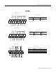
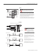
IN 7
IN 5
IN 3
IN 1
AC
COM
IN 6
IN 4
IN 2
IN 0
L1
L2
100/120V ac
AC
COM
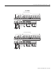
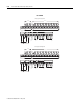
Commons are
connected
internally.
Be careful when stripping wires. Wire fragments that fall into a
module could cause damage when power is applied. Once wiring
is complete, ensure the module is free of all metal fragments.
A current limiting resistor can be used to limit inrush current; however, the operating
characteristics of the ac input circuit will be affected. If a 6.8KΩ resistor is placed in
series with the input, the inrush current is reduced to 35 mA. In this configuration the
minimum on-state voltage increases to 92V ac. Before adding the resistor in a hazardous
environment, be sure to consider the operating temperature of the resistor and the
temperature limits of the environment. The operating temperature of the resistor must
remain below the temperature limit of the environment.
Also, this product is intended to be mounted to a well-grounded mounting surface
such as a metal panel. Additional grounding connections from the module’s mounting tabs
or DIN rail (if used) are not required unless the mounting surface cannot be grounded.
1762-IA8
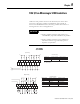
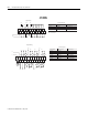
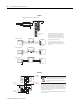
Analog Load
V out 1
V out 0
IN 1 +
IN 0 +
I out 1
I out 0
IN 1 -
IN 0 -
COM
COM
Commons connected
internally.
Differential Sensor Transmitter Types
Analog Sensor
Grounding the cable shield at the module end only usually
provides sufficient noise immunity. However, for best cable
shield performance, earth ground the shield at both ends,
using a 0.01µF capacitor at one end to block AC power ground
currents, if necessary.
All power supplies rated N.E.C. Class 2.
Select the input type, current or voltage, using the switch
located on the module’s circuit board and the input type/range
selection bits in the Configuration Data File.
The output type selection, current or voltage, is made by
wiring to the appropriate terminals, Iout or Vout, and by the
type/range selection bits in the Configuration Data File.
Analog outputs may fluctuate for less than
a second when power is applied or removed.
This characteristic is common to most
analog outputs. While the majority of loads
will not recognize this short signal, it is
recommended that preventive measures be
taken to ensure that connected equipment
is not affected.
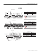
+
+
-
-
+
-
+
-
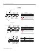
IN +
IN -
COM
+
-
IN +
IN -
COM
+
-
IN +
IN -
COM
Power
Supply
(1)
Power
Supply
(1)
Power
Supply
(1)
Transm itter
Transm itter
Transm itter
Module
Module
Module
Supply Signal
Supply Signal
2-Wire Transmitter
3-Wire Transmitter
4-Wire Transmitter
1762-IF2OF2