
User manual

Publication CIG-WD001B-EN-P - May 2005
7-22 1756 ControlLogix I/O Modules
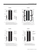
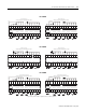
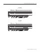
17 (Refere nce+)
A
19 (Reference-)
B
14 (Sine+ )
F
16 (Sine-)
D
18 (Cosin e+)
E
20 (Cosi ne- )
G
Do not use
Sine +
Sine –
Cosine +
Cosine –
12
34
5
6
7
8
910
11
12
1314
1516
1718
19
20
Allen-Brad ley Res olver
846-S JDA1CG-R3-C
F (S3)
D (S1)
E (S2)
G (S4)
A (R1)
B (R2)
Reference +
Reference –
Do not use
Do not use
Do not use
Do not use
Do not use
Do not use
Do not use
Do not use
Do not use
Do not use
Do not use
Do not use
Do not use
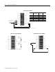
RTB Terminal
Number
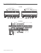
846-SJxNxCG-R3
846-SAxNxCG-R3
Allen-Bradley Resolvers
Designation
845-CA-E-25
845-CA-F-25
Connector Cables
Color Pairs
Resolver
Signal Name
White
Black of white
Black of red
Red
Green
Black of green
R1
R2
S3
S1
S2
S4
NOTE: Do not connect more than 2 wires to any single terminal.
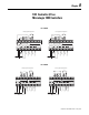
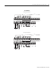
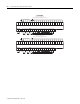
1756-PLS Resolver Module
+
_
+
_
OUTPUT 0
OUTPUT 1
OUTPUT 2
OUTPUT 3
DC PWR 0-3 DC COM 0-3
INPUT 1
INPUT 0
OUTPUT 4
OUTPUT 7
DC PWR 4-7
OUTPUT 5
OUTPUT 6
INPUT 2
INPUT 3
INPUT 4
INPUT 5
INPUT 6
INPUT 7
DC COM 4-7
12
34
5
6
7
8
910
11
12
1314
1516
1718
19
20
10- 30V dc
NOTE: Do not connect more than 2 wires to any single terminal.
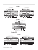
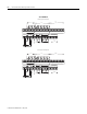
+
_
OUTPUT 8
OUTPUT 9
OUTPUT 10
OUTPUT 11
DC PWR 8-11 DC COM 8-11
INPUT 9
INPUT 8
OUTPUT 12
OUTPUT 15
DC PWR 12- 15
OUTPUT 13
OUTPUT 14
INPUT 10
INPUT 11
INPUT 12
INPUT 13
INPUT 14
INPUT 15
DC COM 12-15
12
34
5
6
7
8
910
11
12
1314
1516
1718
19
20
NOTE: Do not connect more than 2 wires to any single terminal.
1756-PLS Left Section I/O Module 1756-PLS Right Section I/O Module