
User manual

Publication CIG-WD001B-EN-P - May 2005
1756 ControlLogix I/O Modules 7-19
12
34
56
78
910
1112
1314
1516
1718
1920
i
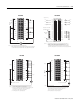
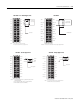
OUT-1
ALT-1
RTN-1
OUT-3
RTN-3
Not used
OUT-5
ALT-5
ALT-3
RTN-5
OUT-0
ALT-0
RTN-0
OUT-2
RTN-2
Not used
OUT-4
ALT-4
ALT-2
RTN-4
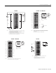
User Analog
Output Device
Shield Ground
1. Place additional devices anywhere in the loop.
NOTES:
2.
Do not connect more than 2 wires to any single terminal.
12
34
56
78
910
1112
1314
1516
1718
1920
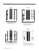
+
–
Shield Ground
OUT-1
Not used
RTN-1
OUT-3
RTN-3
Not used
OUT-5
Not used
Not used
RTN-5
OUT-0
Not used
RTN-0
OUT-2
RTN-2
Not used
OUT-4
Not used
Not used
RTN-4
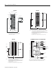
User Analog
Output Device
NO TE S: Do not connect more than 2 wires to any single terminal.
1756-OF6CI – 551 - 1000Ω Applications
1756-OF6VI
12
34
5
6
7
8
910
11
12
1314
1516
1718
19
20
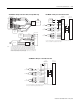
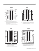
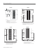
Shield ground
i
Current
output
load
VOUT-4
IOUT-4
RTN
VOUT-5
VOUT-6
IOUT-6
RTN
VOUT-7
IOUT-5
IOUT-7
VOUT-0
IOUT-0
RTN
VOUT-1
VOUT-2
IOUT-2
RTN
VOUT-3
IOUT-1
IOUT-3
Place additional loop devices (e.g strip chart recorders) at the A
location shown above.
A
NOTES:
2. Do not connect more than 2 wires to any single terminal.
3. All RTN terminals are connected internally.
1.
12
34
5
6
7
8
910
11
12
1314
1516
1718
19
20
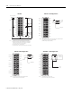
+
–
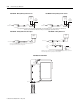
Shield ground
Not used
Not used
Not used
Not used
Not used
Not used
Not used
Not used
VOUT-0
IOUT-0
RTN
VOUT-1
VOUT-2
IOUT-2
RTN
VOUT-3
IOUT-1
IOUT-3
NOTES: 1. Do not connect more than 2 wires to any single terminal.
2.
All RTN terminals are connected internally.
RTN
RTN
1756-OF8 – Current Applications
1756-OF8 – Voltage Applications