
User manual

Publication CIG-WD001B-EN-P - May 2005
7-16 1756 ControlLogix I/O Modules
12
34
5
6
78
910
1112
1314
1516
1718
1920
2122
2324
2526
2728
2930
31
32
3334
3536
+
–
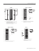
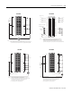
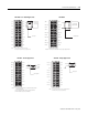
1. All terminals with the same name are connected together on the module. For example,
DC COM can be connected to either terminal marked GND-1.
2. When you daisy chain to other RTBs, always connect the daisy chain to the terminal
directly connected to the supply wire, as shown in the example above.
3. This wiring example shows a single voltage source.
4. If separate power sources are used, do not exceed the specified isolation voltage.
Daisy chain to other RTBs
DC COM
Group 0 Group 0
Group 1 Group 1
+DC-0
+DC-0
+DC-0
+DC-0
+DC-1
+DC-0
+DC-0
+DC-0
GND-0
Not used
+DC-1
+DC-1
+DC-1
+DC-1
+DC-1
+DC-1
GND-1
GND-1
OUT-0
OUT-1
OUT-2
OUT-3
OUT-8
OUT-4
OUT-5
OUT-6
OUT-7
Not used
OUT-9
OUT-10
OUT-11
OUT-12
OUT-13
OUT-14
OUT-15
Not used
Daisy chain to other RTBs
NOTES
Do not connect more than 2 wires to any single terminal.
12
34
5
6
7
8
910
11
12
1314
1516
1718
19
20
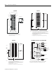
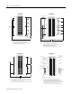
1. All terminals with the same name are connected together on the module. For
example, L1 can be connected to any terminal marked L1-0.
2. When you daisy chain from a group to another RTB, always connect the daisy
chain to the terminal directly connected to the supply wire, as shown above.
3. This wiring example shows a single voltage source.
Daisy chain to other RTBs
Group 0Group 0
Group 1Group 1
L2
Not used
L1-0
L1-0
L1-0
L1-1
L1-1
L1-1
L1-1
L1-0
L1-1
L2-0
OUT-0
OUT-1
OUT-2
OUT-4
OUT-5
OUT-6
OUT-7
OUT-3
L2-1
Daisy
chain to
other
RTBs
L1
NOTES:
Do not connect more than 2 wires to any single terminal.
1756-OA8E 1756-OB16D
12
34
5
6
7
8
910
11
12
1314
1516
1718
19
20
+
–
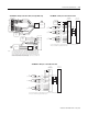
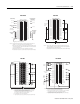
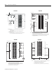
1. When you daisy chain from a group to another RTB, always connect the daisy
chain as shown above. Do not connect more than 2 wires to any single terminal.
2. This wiring example shows a single voltage source.
3. If separate power sources are used, do not exceed the specified isolation voltage.
Daisy chain to
other RTBs
Group 0Group 0
Group 1Group 1
DC COM
OUT-1
OUT-3
OUT-5
OUT-7
OUT-9
OUT-11
OUT-13
OUT-15
DC-0(+)
DC-1(+)
OUT-0
OUT-2
OUT-4
OUT-6
OUT-8
OUT-10
OUT-12
OUT-14
RTN OUT-0
RTN OUT-1
NOTES:
1
2
3
4
5
6
7
8
9
10
11
12
13
14
15
16
17
18
19
20
21
22
23
24
25
26
27
28
29
30
31
32
33
34
35
36
+
–
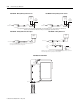
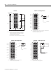
Non-i solated
wir ing
Isolat ed wir ing
1. All terminals with the same name are connected together on the module. For
example, DC (+) can be connected to either terminal marked DC-15.
2. When you use the second DC-15 (+) terminal to daisy chain to other RTBs, always
connect the daisy chain to the terminal directly connected to the supply wire, as
shown in the example above.
3. Outputs can be wired in a sink or source configuration as shown above.
4. If separate power sources are used, do not exceed the specified isolation voltages.
Daisy chain to other RTBs
DC-0 (+)
DC-1 (+)
DC-2 (+)
DC-3 (+)
DC-8 (+)
DC-4 (+)
DC-5 (+)
DC-6 (+)
DC-7 (+)
Not used
DC-9 (+)
DC-10 (+)
DC-11 (+)
DC-12 (+)
DC-13 (+)
DC-14 (+)
DC-15 (+)
DC-15 (+)
OUT-0
OUT-1
OUT-2
OUT-3
OUT-8
OUT-4
OUT-5
OUT-6
OUT-7
Not used
OUT-9
OUT-10
OUT-11
OUT-12
OUT-13
OUT-14
OUT-15
Not used
DC-0 (+)
DC(+)
DC-2 (+)
DC-6 (+)
Sin king outp ut wir ing
Non-isol ated
sourc ing
outp ut
wir ing
Isol ated sour cing
out put wir ing
DC-0 (-)
DC-2 (-)
DC-6 (-)
DC(-)
NOTES:
Do not connect more than 2 wires to any single terminal.
Jumper bar - Cut to length
(Part number 97739201)
1756-OB16E 1756-OB16I