
User manual

Publication CIG-WD001B-EN-P - May 2005
1756 ControlLogix I/O Modules 7-13
5V DC
Field Power
Supply
+5V DC
+5 COM
RED
BLK
To fault
string
OK
RED
BLK
WHT
BLK
RED
BLK
WHT
BLK
RED
BLK
GRN
BLK
+OUT 0
-OUT 0
+ENABLE 0
-ENABLE 0
DRVFLT 0
CHASSIS
IN_COM
HOME 0
REG24V 0
REG5V 0
+OK
CHASSIS
+CHA 0
-CHA 0
+CHB 0
-CHB 0
+CHZ 0
-CHZ 0
+OUT 1
-OUT 1
+ENABLE 1
-ENABLE 1
DRVFLT 1
CHASSIS
IN_COM
HOME 1
REG24V 1
REG5V 1
-OK
CHASSIS
+CHA 1
-CHA 1
+CHB 1
-CHB 1
+CHZ 1
-CHZ 1
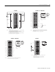
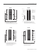
Servo Module RTB
1394CCAExx
24V DC
Field Power
Supply
1394 Ser vo Drive
1394CCAExx
WHT
BLK
RED
BLK
+ENABLE 1
-ENABLE 1
DRVFLT 1
IN_COM
TB2 7
TB2 19
TB2 18
W2
W1
TB2 15
24V DC
24V COM
24V DC
24V COM
24V ENABLE COM
A1 ENABLE
DROK
DROK
AQB1
A
RED OK+
BLK OK-
1756-M02AE
Axis 1
ENA/DR OK 1
ENC. PWR -1
A
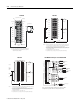
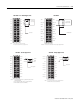
1. The wiring diagram illustrates Axis 1 wiring only. Other configurations are possible.
2. The 1394-CCAExx cable is wired to connect to torque command reference input pins.
3. An external +5V power supply is required to power the encoder driver circuit of the
1394 servo drive.Because this connection is shared by all four axis encoder driver circuits,
only one connection is needed to the +5V field supply.
4. The xx in the cable number is the length of the cable. Options are 5, 10, 25 and 50 feet.
NOTES:
1756-MO2AE – Wiring to 1394 Servo Drive (in Torque Mode only)
24 VDC
Field Power Supply
24VDC
READY+
24VCOM
COMMAND+
COMMAND-
ENABLE
READY-
AOUT+
AOUT-
BOUT+
BOUT-
IOUT+
IOUT-
24VDC
24VCOM
24 VDC
24 VCOM
+OUT
-OUT
+ENABLE
-ENABLE
DRVFLT
IN_COM
+CHA
-CHA
+CHB
-CHB
+CHZ
-CHZ
J1-5
J1-26
J1-24
J1-6
J1-13
J1-22
J1-23
J1-20
J1-25
J1-7
J1-8
J1-9
J1-10
J1-11
J1-12
General Cable
C0720
General Cable
C0721
General Cable
C0722
From
1756-M02AE
From
1756-M02AE
From
1756-M02AE
J1 to 50-pin
Terminal Block
(Kit P/N 9109-1391)
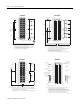
Ultra 100 Series
Digital Servo Drive
Interface
Cable
P/N 9109-1369-003
J1
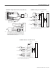
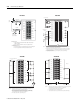
This is general wiring example only. Other configurations are possible. For more information, refer to the
Ultra 100 series installation manual, publication number 1398-5.2.
1756-MO2AE – Wiring to an Ultra 100 Series Drive
J1 to 50-pin
Terminal Block
(Kit P/N 9109-1391)
24VDC
READY+
24VCOM
COMMAND+
COMMAND-
ENABLE
READY-
AOUT+
AOUT-
BOUT+
BOUT-
IOUT+
IOUT-
+OUT
-OUT
+ENABLE
-ENABLE
DRVFLT
IN_COM
+CHA
-CHA
+CHB
-CHB
+CHZ
-CHZ
J1-5
J1-24
J1-6 or 13
J1-22
J1-23
J1-20
J1-25
J1-7
J1-8
J1-9
J1-10
J1-11
J1-12
General Cable
C0720
General Cable
C0721
General Cable
C0722
From
1756-M02AE
From
1756-M02AE
From
1756-M02AE
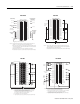
Ultra 200 Series
Digital Servo Drive
Interface
Cable
P/N 9109-1369-003
J1
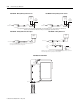
This is general wiring example only. Other configurations are possible. For more information, refer to the
Ultra 200 series installation manual, publication number 1398-5.0.
1756-MO2AE – Wiring to an Ultra 200 Series Drive