
User manual

Publication CIG-WD001B-EN-P - May 2005
7-12 1756 ControlLogix I/O Modules
21
10 9
87
65
43
12 11
14 13
16 15
18 17
20 19
+
–
Cold junction
sensor
Thermocouple
Wire
Not used
CJC–
RTN-0
RTN-1
RTN-2
RTN-3
RTN-4
RTN-5
CJC–
Not used
Spade Lug
Not used
CJC+
IN-0
IN-1
IN-2
IN-3
IN-4
IN-5
CJC+
Not used
Cold junction sensor
Wire Spade Lug
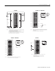
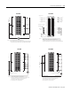
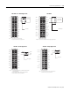
NOTES:
1. Do not connect more than 2 wires to any single terminal.
2. The part number for the cold junction sensor used on the
1756-IT6I2 module is 94286501.
1756-IT6I2
12
34
5
6
7
8
910
11
12
1314
1516
1718
19
20
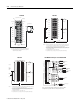
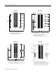
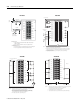
1. All terminals with the same name are connected together on the module. For example, DC
(+) can be connected to either terminal marked DC-1+. If you are daisy chain wiring from
one of these terminals to other RTBs, only connect wiring to one terminal.
2. When you daisy chain from a group to another RTB, always connect the daisy chain to the
terminal directly connected to the supply wire, as shown above.
3. This wiring example shows a single voltage source.
4. If separate power sources are used, do not exceed the specified isolation voltage.
–+
Daisy chain to other RTBs
Group 0Group 0
Group 1Group 1
DC COM
IN-0
IN-2
IN-4
IN-6
DC-0 +
IN-8
IN-10
IN-12
IN-14
DC-1 +
IN-1
IN-3
IN-5
IN-7
DC-0 +
IN-9
IN-11
IN-13
IN-15
DC-1 +
NOTES:
Do not connect more than
2 wires to any single terminal.
1756-IV16
12
34
56
78
910
1112
1314
1516
1718
1920
2122
2324
2526
2728
2930
3132
3334
3536
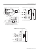
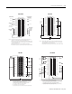
1. All terminals with the same name are connected together on the module. For example,
DC (+) can be connected to either terminal marked DC-1 (+).
2. Do not physically connect more than two wires to a single RTB terminal. When
jumpering I/O groups together and daisy chain wiring to adjacent modules, follow the
wiring method shown above.
3. This wiring example shows a single voltage source.
4. If separate power sources are used, do not exceed the specified isolation voltage.
+
–
Daisy
chain to
other
RTBs
DC COM
Group 0 Group 0
Group 1 Group 1
IN-1
IN-3
IN-5
IN-7
DC-0 (+)
IN-9
IN-11
IN-13
IN-15
DC-1 (+)
IN-17
IN-19
IN-21
IN-23
IN-25
IN-27
IN-29
IN-31
IN-0
IN-2
IN-4
IN-6
DC-0 (+)
IN-8
IN-10
IN-12
IN-14
DC-1 (+)
IN-16
IN-18
IN-20
IN-22
IN-24
IN-26
IN-28
IN-30
NOTES:
Jumper
wire
1756-IV32
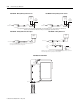
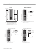
General Cable
C0720
To servo drive
To servo drive
To home
limit switch
To registration
sensor
To encoder
To E-stop relay coil
General Cable
C0720
General Cable
C0720
General Cable
C0720
General Cable
C0722
General Cable
C0721
2
4
6
8
10
12
14
16
18
20
22
24
26
28
30
32
34
36
1
3
5
7
9
11
13
15
17
19
21
23
25
27
29
31
33
35
+OUT-0
-OUT-0
+ENABLE-0
-ENABLE-0
DRVFLT-0
CHASSIS
IN_COM
HOME-0
REG24V-0
REG5V-0
+OK
CHASSIS
+CHA-0
-CHA-0
+CHB-0
-CHB-0
+CHZ-0
-CHZ-0
-OK
+OUT-1
-OUT-1
+ENABLE-1
-ENABLE-1
DRVFLT-1
CHASSIS
IN_COM
HOME-1
REG24V-1
REG5V-1
CHASSIS
+CHA-1
-CHA-1
+CHB-1
-CHB-1
+CHZ-1
-CHZ-1
This is a general wiring example illustrating Axis 1 wiring only. Other
configurations are possible with Axis 0 wiring identical to Axis 1.
1756-MO2AE – Wiring to a Servo Module RTB