
User manual

Publication CIG-WD001B-EN-P - May 2005
7-10 1756 ControlLogix I/O Modules
12
34
56
78
910
1112
1314
1516
1718
1920
2122
2324
2526
2728
2930
3132
3334
3536
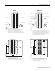
Non- isolated
wi ring
Isolat ed
wir ing
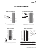
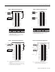
1. All terminals with the same name are connected together on the module. For
example, DC (-) can be connected to either terminal marked GND-15.
2. When you use the second GND-15 terminal to daisy chain to other RTBs, always
connect the daisy chain to the terminal directly connected to the supply wire, as
shown in the example above.
3. If separate power sources are used, do not exceed the specified isolation voltage.
Daisy chain to other RTBs
DC (-)
Jumper bar
(Cut to length)
DC-7 (-) DC-7 (+)
DC (+)
DC-0 (+)
DC-3 (+)
DC-0 (-)
DC-3 (-)
IN-0
IN-1
IN-2
IN-3
IN-8
IN-4
IN-5
IN-6
IN-7
Not used
IN-9
IN-10
IN-11
IN-12
IN-13
IN-14
IN-15
Not used
GND-0
GND-1
GND-2
GND-3
GND-8
GND-4
GND-5
GND-6
GND-7
Not used
GND-9
GND-10
GND-11
GND-12
GND-13
GND-14
GND-15
GND-15
NOTES:
Do not connect more than 2 wires to any single terminal.
1
3
5
7
9
19
17
15
13
11
2
4
6
8
10
20
18
16
14
12
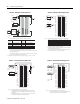
IN-1
IN-3
IN-5
IN-7
DC-0(+)
IN-0
IN-2
IN-4
IN-6
DC COM 0
IN-9
IN-11
IN-13
IN-15
DC-1(+)
IN-8
IN-10
IN-12
IN-14
DC COM 1
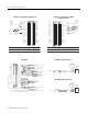
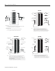
GENERAL NOTES:
1. We recommend you use Belden M 8761 cable where shielded cables are shown.
2. Do not connect more than two wires to any single terminal.
CE REQUIREMENT NOTES:
1. DC power wire and I/O wire should not exceed 10m (30ft) in length.
2. The 0.01
µ
F capacitors shown above must be rated for 2000V dc.
Capacitor
0.01
µ F typical
(See notes below)
5V dc power
DC power wire
I/O wire
+
–
1756-IH16I1756-IG16
12
34
56
78
910
1112
1314
1516
1718
1920
2122
2324
2526
2728
2930
3132
3334
3536
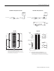
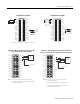
Non-isol ated
wir ing
Isolate d wiri ng
1. All terminals with the same name are connected together on the module. For
example, L2 can be connected to either terminal marked L2-15.
2. When you use the second L2-15 terminal to daisy chain to other RTBs, always
connect the daisy chain to the terminal directly connected to the supply wire, as
shown in the example above.
3. If separate power sources are used, do not exceed the specified isolation voltage.
Daisy chain to other RTBs
L2-0
L2-0
L2-1
L2-2
L2-3
L2-8
L2-4
L2-5
L2-6
L2-7
Not used
L2-9
L2-10
L2-11
L2-12
L2-13
L2-14
L2-15
L2-15
IN-0
IN-1
IN-2
IN-3
IN-8
IN-4
IN-5
IN-6
IN-7
Not used
IN-9
IN-10
IN-11
IN-12
IN-13
IN-14
IN-15
Not used
L2-2
L2-4
L2
L1
L1-0
L1-2
L1-4
Jumper bar
(Cut to length)
NOTES:
Do not connect more than 2 wires to any single terminal.
12
34
56
78
910
1112
1314
1516
1718
1920
2122
2324
2526
2728
2930
3132
3334
3536
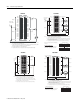
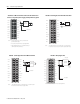
Isolated wiring
Daisy chain to other RTBs
DC (-)
DC-6 (-) DC-6 (+)
DC (+)
DC-0 (+)
DC-0 (-)
IN-0
IN-1
IN-2
IN-3
IN-8
IN-4
IN-5
IN-6
IN-7
Not used
IN-9
IN-10
IN-11
IN-12
IN-13
IN-14
IN-15
Not used
GND-0
GND-1
GND-2
GND-3
GND-8
GND-4
GND-5
GND-6
GND-7
Not used
GND-9
GND-10
GND-11
GND-12
GND-13
GND-14
GND-15
GND-15
Sink input wiring
Source input wiringSource input wiring
Sink input wiring
NOTES: 1. All terminals with the same name are connected together on the module. For
example, DC (-) can be connected to either terminal marked GND-15.
2. When you use the second GND-15 terminal to daisy chain to other RTBs, always
connect the daisy chain to the terminal directly connected to the supply wire, as
shown in the example above.
3. If separate power sources are used, do not exceed the specified isolation voltage.
4. Do not connect more than 2 wires to any single terminal.
5. The jumper bar is part number 97739201; use this number to order additional bars.
Non-isolated
wiring
Jumper bar
(Part number 97739201)
1756-IM16I1756-IH16ISOE