
User manual

Publication CIG-WD001B-EN-P - May 2005
1756 ControlLogix I/O Modules 7-9
12
34
56
78
910
1112
1314
1516
1718
1920
2122
2324
2526
2728
2930
3132
3334
3536
+
–
+
–
Shield ground
Channel 0
Channel 3
IN-0
IN-1
IN-2
IN-3
IN-7
RTN
IN-4
IN-5
IN-6
Not used
Not used
Not used
Not used
Not used
Not used
Not used
Not used
Not used
i RTN-0
i RTN-1
i RTN-2
i RTN-3
i RTN-7
RTN
i RTN-4
i RTN-5
i RTN-6
Not used
Not used
Not used
Not used
Not used
Not used
Not used
Not used
Not used
Shield ground
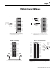
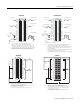
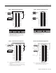
1. Use the following chart when wiring your module in differ ential mode
2. When operating in 2 channel, high speed mode, only use channels 0 and 2.
3. All terminals marked RTN are connected internally.
4.
If multiple (+) or multiple (-) terminals are tied together, connect that tie point to a RTN
terminal to maintain the module’s accuracy.
Thi s channel: Uses t hese terminals: Thi s channel: Uses these terminals:
Channel 0 IN-0 IN-1 & Channel 2
Channel 1 Channel 3
NOTES:
IN-2 IN-3 &
IN-4 IN-5 &
IN-6 IN-7 &
5. Terminal marked RTN or i RTN are not used in differential voltage applications.
6. Do not connect more than 2 wires to any single terminal.
2
4
6
8
10
12
14
16
18
20
22
24
26
28
30
32
34
36
A
Shield
ground
Channel 0
Channel 3
Jumper
wires
2-Wire
Transmitter
IN-0
IN-1
IN-2
IN-3
IN-7
RTN
IN-4
IN-5
IN-6
Not used
Not used
Not used
Not used
Not used
Not used
Not used
Not used
Not used
1
3
5
7
9
11
13
15
17
19
21
23
25
27
29
31
33
35
i RTN-0
i RTN-1
i RTN-2
i RTN-3
i RTN-7
RTN
i RTN-4
i RTN-5
i RTN-6
Not used
Not used
Not used
Not used
Not used
Not used
Not used
Not used
Not used
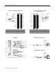
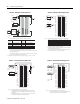
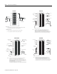
1. Use the following chart when wiring your module in differential mode
2. When operating in 2 channel, high speed mode, only use channels 0 and 2.
3. All terminals marked RTN are connected internally.
4. A 249Ω current loop resistor is located between IN-x and i RTN-x terminals.
5. If multiple (+) or multiple (-) terminals are tied together, connect that tie point to a RTN
terminal to maintain the module’s accuracy.
6. Place additional loop devices (e.g. strip chart recorders, etc.) at A location.
7. If separate power sources are used, do not exceed the specified isolation voltage.
This channel: Uses these terminals: This channel : Uses these ter minals:
Channel 0 IN-0, IN-1 & i RTN-0 Channel 2 IN-4, IN-5 & i RTN-4
Channel 1 IN-2, IN-3 & i RTN-2 Channel 3 IN-6, IN-7 & i RTN-6
NOTES:
the
i
A
i
8. Do not connect more than 2 wires to any single terminal.
To field
device
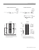
1756-IF8 – Differential Current Applications 1756-IF8 – Differential Voltage Applications
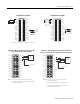
1. All terminals marked RTN are connected internally.
2. Terminals marked iRTN are not used for single-ended voltage wiring.
12
34
56
78
910
1112
1314
1516
1718
1920
2122
2324
2526
2728
2930
3132
3334
3536
+
–
+
–
IN-0
IN-1
IN-2
IN-3
IN-7
RTN
IN-4
IN-5
IN-6
Not used
Not used
Not used
Not used
Not used
Not used
Not used
Not used
Not used
i RTN-0
i RTN-1
i RTN-2
i RTN-3
i RTN-7
RTN
i RTN-4
i RTN-5
i RTN-6
Not used
Not used
Not used
Not used
Not used
Not used
Not used
Not used
Not used
Shield ground
Channel 0
Channel 1
Shield ground
NOTES:
3. Do not connect more than 2 wires to any single terminal.
12
34
56
78
910
1112
1314
1516
1718
1920
2122
2324
2526
2728
2930
3132
3334
3536
i
i
A
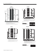
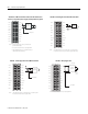
1. All terminals marked RTN are connected internally.
2. For current applications, all terminals marked iRTN must be wired to terminals
marked RTN.
3. A 249Ω current loop resistor is located between IN-x and i RTN-x terminals.
4. Place additional loop devices (e.g. strip chart recorders, etc.) at the A location.
Shield ground
Channel 0
Channel 5
Jumper
wires
2-Wire
Transmitter
IN-0
IN-1
IN-2
IN-3
IN-7
RTN
IN-4
IN-5
IN-6
Not used
Not used
Not used
Not used
Not used
Not used
Not used
Not used
Not used
i RTN-0
i RTN-1
i RTN-2
i RTN-3
i RTN-7
RTN
i RTN-4
i RTN-5
i RTN-6
Not used
Not used
Not used
Not used
Not used
Not used
Not used
Not used
Not used
NOTES:
5. Do not connect more than 2 wires to any single terminal.
To field
device
1756-IF8 – Single-Ended Current Applications 1756-IF8 – Single-Ended Voltage Applications